Cirkit Designer Logo
Cirkit Designer
Your all-in-one circuit design IDE
Home / 
Component Documentation

How to Use Digital Push Button Switch module: Examples, Pinouts, and Specs

Image of Digital Push Button Switch module
Cirkit Designer LogoDesign with Digital Push Button Switch module in Cirkit Designer

Introduction

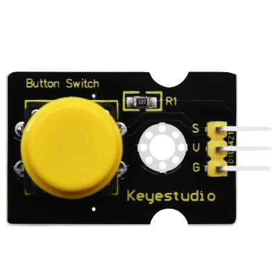
The Keyestudio Digital Push Button Switch Module (Part ID: KS0029) is a versatile electronic component designed to provide a simple and reliable way to control circuits. By pressing the button, the module generates a digital signal (HIGH or LOW) that can be used to trigger various actions in a circuit. This module is ideal for applications requiring user input, such as toggling LEDs, controlling motors, or interacting with microcontrollers like Arduino.

Explore Projects Built with Digital Push Button Switch module

Use Cirkit Designer to design, explore, and prototype these projects online. Some projects support real-time simulation. Click "Open Project" to start designing instantly!
Battery-Powered LED Control with Pushbutton and Relay
Image of EXP.3 E: A project utilizing Digital Push Button Switch module in a practical application
This circuit uses a pushbutton to control a 5V relay, which in turn powers a red LED. The MAHIR 1.mini module provides the necessary 3.7V power supply, and the relay switches the LED on and off based on the pushbutton input.
Cirkit Designer LogoOpen Project in Cirkit Designer
Battery-Powered Multi-Button Controller with Seeed Studio nRF52840
Image of RetroBle Atari Controller: A project utilizing Digital Push Button Switch module in a practical application
This circuit consists of five pushbuttons connected to a Seeed Studio nRF52840 microcontroller, which is powered by a Polymer Lithium Ion Battery. Each pushbutton is connected to a different GPIO pin on the microcontroller, allowing for individual button press detection and processing.
Cirkit Designer LogoOpen Project in Cirkit Designer
Arduino UNO and ESP8266 NodeMCU Interactive Display with Pushbutton Inputs and Audio Feedback
Image of Tetris game: A project utilizing Digital Push Button Switch module in a practical application
This circuit features an Arduino UNO microcontroller interfaced with multiple pushbuttons, a piezo buzzer, an LED dot display, and an ESP8266 NodeMCU. The pushbuttons are likely used for input to trigger different actions or events, the piezo buzzer for audible feedback, and the LED dot display for visual output. The ESP8266 NodeMCU is connected to the Arduino UNO for potential WiFi capabilities, expanding the functionality for IoT applications.
Cirkit Designer LogoOpen Project in Cirkit Designer
Wi-Fi and GSM Controlled Smart Relay with LCD Display
Image of izdelie_2: A project utilizing Digital Push Button Switch module in a practical application
This circuit integrates an ESP8266 WiFi module, a SIM800c GSM module, and a 16x2 LCD display to create a remote-controlled system with a menu interface. The system uses pushbuttons for user input, controls a relay for switching operations, and communicates via MQTT for remote monitoring and control.
Cirkit Designer LogoOpen Project in Cirkit Designer

Explore Projects Built with Digital Push Button Switch module

Use Cirkit Designer to design, explore, and prototype these projects online. Some projects support real-time simulation. Click "Open Project" to start designing instantly!
Image of EXP.3 E: A project utilizing Digital Push Button Switch module in a practical application
Battery-Powered LED Control with Pushbutton and Relay
This circuit uses a pushbutton to control a 5V relay, which in turn powers a red LED. The MAHIR 1.mini module provides the necessary 3.7V power supply, and the relay switches the LED on and off based on the pushbutton input.
Cirkit Designer LogoOpen Project in Cirkit Designer
Image of RetroBle Atari Controller: A project utilizing Digital Push Button Switch module in a practical application
Battery-Powered Multi-Button Controller with Seeed Studio nRF52840
This circuit consists of five pushbuttons connected to a Seeed Studio nRF52840 microcontroller, which is powered by a Polymer Lithium Ion Battery. Each pushbutton is connected to a different GPIO pin on the microcontroller, allowing for individual button press detection and processing.
Cirkit Designer LogoOpen Project in Cirkit Designer
Image of Tetris game: A project utilizing Digital Push Button Switch module in a practical application
Arduino UNO and ESP8266 NodeMCU Interactive Display with Pushbutton Inputs and Audio Feedback
This circuit features an Arduino UNO microcontroller interfaced with multiple pushbuttons, a piezo buzzer, an LED dot display, and an ESP8266 NodeMCU. The pushbuttons are likely used for input to trigger different actions or events, the piezo buzzer for audible feedback, and the LED dot display for visual output. The ESP8266 NodeMCU is connected to the Arduino UNO for potential WiFi capabilities, expanding the functionality for IoT applications.
Cirkit Designer LogoOpen Project in Cirkit Designer
Image of izdelie_2: A project utilizing Digital Push Button Switch module in a practical application
Wi-Fi and GSM Controlled Smart Relay with LCD Display
This circuit integrates an ESP8266 WiFi module, a SIM800c GSM module, and a 16x2 LCD display to create a remote-controlled system with a menu interface. The system uses pushbuttons for user input, controls a relay for switching operations, and communicates via MQTT for remote monitoring and control.
Cirkit Designer LogoOpen Project in Cirkit Designer

Common Applications and Use Cases

  • User input for microcontroller-based projects
  • Triggering events in automation systems
  • Controlling LEDs, buzzers, or relays
  • Prototyping and educational projects
  • Simple on/off control in DIY electronics

Technical Specifications

The following table outlines the key technical details of the Keyestudio Digital Push Button Switch Module:

Parameter Specification
Operating Voltage 3.3V to 5V
Output Signal Digital (HIGH: 5V, LOW: 0V)
Button Type Momentary (non-latching)
Dimensions 24mm x 15mm
Mounting Holes 2 holes for easy installation
Interface Type 3-pin header (VCC, GND, Signal)

Pin Configuration and Descriptions

The module has a 3-pin interface, as described in the table below:

Pin Name Description
1 VCC Connect to the positive supply voltage (3.3V or 5V).
2 GND Connect to the ground of the power supply.
3 Signal Outputs a digital signal (HIGH or LOW) based on the button's state.

Usage Instructions

How to Use the Component in a Circuit

  1. Wiring the Module:

    • Connect the VCC pin to the 5V or 3.3V pin of your power source or microcontroller.
    • Connect the GND pin to the ground of your power source or microcontroller.
    • Connect the Signal pin to a digital input pin on your microcontroller or to the input of another circuit.
  2. Operation:

    • When the button is not pressed, the Signal pin outputs a LOW (0V) signal.
    • When the button is pressed, the Signal pin outputs a HIGH (5V) signal.
  3. Example Circuit:

    • Use the module to control an LED:
      • Connect the Signal pin to a digital input pin on your microcontroller.
      • Write a program to read the button state and toggle the LED accordingly.

Important Considerations and Best Practices

  • Ensure the operating voltage does not exceed the specified range (3.3V to 5V).
  • Use pull-down resistors if necessary to stabilize the signal when the button is not pressed.
  • Avoid excessive mechanical stress on the button to prolong its lifespan.
  • Debounce the button in software to prevent false triggering due to mechanical noise.

Arduino UNO Example Code

Below is an example code snippet for using the module with an Arduino UNO to control an LED:

// Define pin connections
const int buttonPin = 2;  // Signal pin of the button module connected to digital pin 2
const int ledPin = 13;    // Built-in LED on Arduino UNO

void setup() {
  pinMode(buttonPin, INPUT);  // Set button pin as input
  pinMode(ledPin, OUTPUT);    // Set LED pin as output
}

void loop() {
  int buttonState = digitalRead(buttonPin);  // Read the button state

  if (buttonState == HIGH) {
    // If button is pressed, turn on the LED
    digitalWrite(ledPin, HIGH);
  } else {
    // If button is not pressed, turn off the LED
    digitalWrite(ledPin, LOW);
  }
}

Troubleshooting and FAQs

Common Issues and Solutions

  1. The button does not respond when pressed:

    • Check the wiring to ensure all connections are secure and correct.
    • Verify that the power supply voltage is within the operating range (3.3V to 5V).
    • Test the button with a multimeter to ensure it is functioning properly.
  2. The output signal is unstable or fluctuates:

    • Add a pull-down resistor (e.g., 10kΩ) between the Signal pin and GND to stabilize the signal.
    • Implement software debouncing in your microcontroller code to filter out noise.
  3. The module gets hot during operation:

    • Ensure the operating voltage does not exceed 5V.
    • Check for short circuits in the wiring.

FAQs

Q: Can I use this module with a 3.3V microcontroller like the ESP32?
A: Yes, the module is compatible with both 3.3V and 5V systems.

Q: How do I debounce the button in software?
A: You can use a delay or a timer in your code to ignore rapid changes in the button state. For example, add a small delay (e.g., 50ms) after detecting a button press to filter out noise.

Q: Can I use this module to control high-power devices?
A: No, the module outputs a low-power digital signal. Use a relay or transistor circuit to control high-power devices.

This concludes the documentation for the Keyestudio Digital Push Button Switch Module (KS0029).