How to Use Tic T500: Examples, Pinouts, and Specs
Introduction
The Tic T500, manufactured by Pololu, is a compact and high-performance stepper motor driver designed to simplify the control of stepper motors in a wide range of applications. It supports adjustable current control, microstepping, and operates over a broad voltage range, making it versatile and reliable for projects requiring precise motor control. The Tic T500 is particularly well-suited for robotics, CNC machines, 3D printers, and other motion control systems.
Explore Projects Built with Tic T500


Explore Projects Built with Tic T500
Common Applications
- Robotics and automation systems
- CNC machines and milling equipment
- 3D printers
- Conveyor belts and industrial machinery
- Camera sliders and gimbals
Technical Specifications
The following table outlines the key technical details of the Tic T500:
| Parameter | Value |
|---|---|
| Input Voltage Range | 4.5 V to 35 V |
| Maximum Continuous Current | 1.5 A per phase (without additional cooling) |
| Microstepping Modes | Full-step, half-step, 1/4-step, 1/8-step, 1/16-step, 1/32-step |
| Control Interfaces | USB, TTL serial, I²C, analog voltage, RC hobby servo pulses |
| Logic Voltage | 3.3 V or 5 V (compatible with most microcontrollers, including Arduino) |
| Dimensions | 1.2" × 0.6" × 0.2" (30 mm × 16 mm × 5 mm) |
| Operating Temperature Range | -40°C to +85°C |
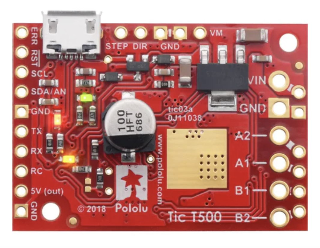
Pin Configuration and Descriptions
The Tic T500 features a variety of pins for power, motor control, and communication. The table below describes the key pins:
| Pin Name | Type | Description |
|---|---|---|
| VIN | Power Input | Main power supply input (4.5 V to 35 V). |
| GND | Power Ground | Ground connection for power and logic. |
| A1, A2 | Motor Output | Outputs for one coil of the stepper motor. |
| B1, B2 | Motor Output | Outputs for the other coil of the stepper motor. |
| TX | Serial Output | Transmit pin for TTL serial communication. |
| RX | Serial Input | Receive pin for TTL serial communication. |
| SCL | I²C Clock | Clock line for I²C communication. |
| SDA | I²C Data | Data line for I²C communication. |
| RC | Input | Input for RC hobby servo pulses. |
| AN | Input | Analog voltage input for speed or position control. |
| USB | Communication | USB interface for configuration and control. |
| RESET | Input | Resets the Tic T500 when pulled low. |
Usage Instructions
How to Use the Tic T500 in a Circuit
- Power Supply: Connect a power source (4.5 V to 35 V) to the VIN and GND pins. Ensure the power supply can provide sufficient current for your stepper motor.
- Motor Connection: Connect the stepper motor's coils to the A1, A2, B1, and B2 pins. Refer to your motor's datasheet to identify the correct wiring.
- Control Interface: Choose a control method (e.g., USB, TTL serial, I²C, analog, or RC). Connect the appropriate pins to your microcontroller or control device.
- Configuration: Use the Pololu Tic Control Center software to configure the Tic T500. This software allows you to set parameters such as current limits, microstepping mode, and control interface.
- Testing: Test the setup by sending commands through your chosen interface. Monitor the motor's behavior and adjust settings as needed.
Important Considerations and Best Practices
- Cooling: If operating near the maximum current limit, consider adding a heatsink or active cooling to prevent overheating.
- Power Supply: Use a power supply with sufficient current capacity to avoid voltage drops or instability.
- Wiring: Keep motor and power wires as short as possible to minimize noise and voltage loss.
- Microstepping: Use higher microstepping modes for smoother motion but be aware that torque may decrease at higher resolutions.
- Safety: Always disconnect power before making changes to the wiring or configuration.
Example: Using the Tic T500 with an Arduino UNO
The following example demonstrates how to control the Tic T500 using an Arduino UNO via TTL serial communication.
Wiring
- Connect the Tic T500's RX pin to the Arduino's TX pin (pin 1).
- Connect the Tic T500's TX pin to the Arduino's RX pin (pin 0).
- Connect the Tic T500's GND pin to the Arduino's GND.
- Connect the stepper motor and power supply as described above.
Code
#include <SoftwareSerial.h>

// Define the Arduino pins connected to the Tic T500
#define TIC_RX_PIN 10 // Arduino pin connected to Tic TX
#define TIC_TX_PIN 11 // Arduino pin connected to Tic RX

// Create a SoftwareSerial object for communication with the Tic T500
SoftwareSerial ticSerial(TIC_RX_PIN, TIC_TX_PIN);

void setup() {
  // Start serial communication with the Tic T500
  ticSerial.begin(9600);

  // Set the stepper motor target position
  setTargetPosition(2000); // Move to position 2000
}

void loop() {
  // Add your main code here (e.g., update position or speed dynamically)
}

// Function to send a "Set Target Position" command to the Tic T500
void setTargetPosition(int32_t targetPosition) {
  ticSerial.write(0xE0); // Command byte for "Set Target Position"
  ticSerial.write((uint8_t)(targetPosition & 0xFF));       // Lowest byte
  ticSerial.write((uint8_t)((targetPosition >> 8) & 0xFF)); // Second byte
  ticSerial.write((uint8_t)((targetPosition >> 16) & 0xFF)); // Third byte
  ticSerial.write((uint8_t)((targetPosition >> 24) & 0xFF)); // Highest byte
}
Troubleshooting and FAQs
Common Issues
Motor Not Moving:
- Ensure the motor is properly connected to the A1, A2, B1, and B2 pins.
- Verify that the power supply voltage and current meet the motor's requirements.
- Check the control interface configuration in the Tic Control Center.
Overheating:
- Reduce the current limit in the Tic Control Center.
- Add a heatsink or active cooling to the Tic T500.
Communication Errors:
- Verify the wiring between the Tic T500 and the control device.
- Ensure the baud rate and other communication settings match.
Motor Vibrates but Does Not Rotate:
- Check the wiring of the stepper motor coils. Incorrect wiring can cause this issue.
- Reduce the microstepping mode to increase torque.
FAQs
Q: Can I use the Tic T500 with a 12 V power supply?
A: Yes, the Tic T500 supports input voltages from 4.5 V to 35 V, so a 12 V power supply is suitable.
Q: How do I reset the Tic T500?
A: Pull the RESET pin low to reset the Tic T500. Alternatively, you can use the reset option in the Tic Control Center software.
Q: What is the maximum step rate supported by the Tic T500?
A: The Tic T500 supports step rates up to 50,000 steps per second, depending on the microstepping mode and motor.
Q: Can I control multiple Tic T500s with one Arduino?
A: Yes, you can control multiple Tic T500s using unique addresses for I²C or separate serial connections.