How to Use LIS3DSH: Examples, Pinouts, and Specs
Introduction
The LIS3DSH is a low-power, 3-axis accelerometer that provides digital output via I2C or SPI interfaces. It is designed for motion sensing applications, offering features such as high sensitivity, programmable full-scale ranges, and built-in self-test capabilities. This versatile sensor is ideal for applications requiring precise motion detection, such as wearable devices, gaming peripherals, robotics, and industrial equipment.
Explore Projects Built with LIS3DSH

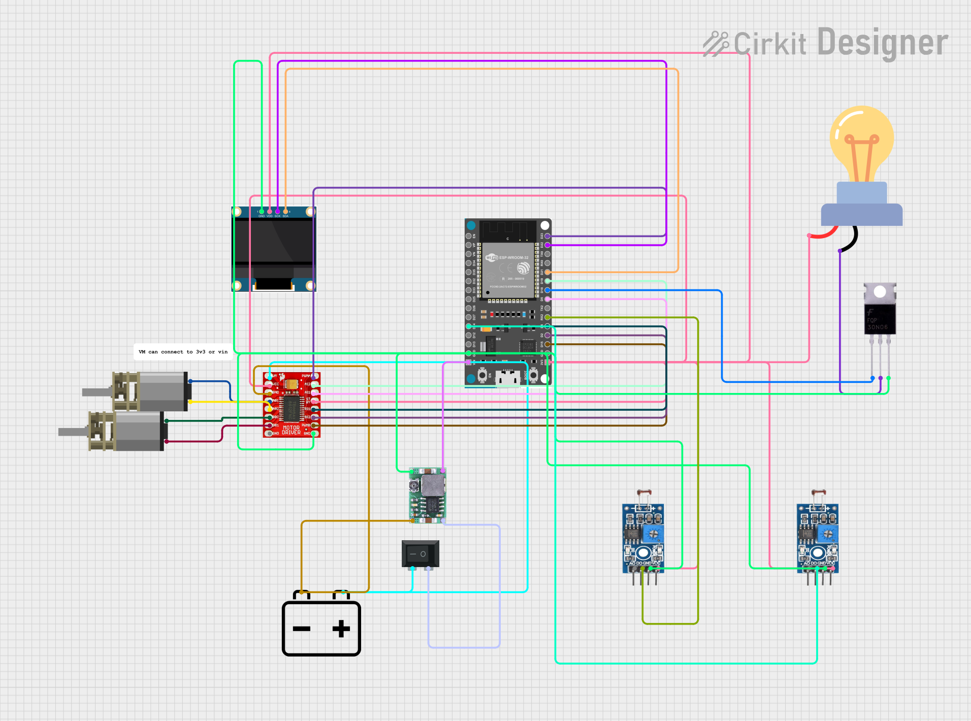
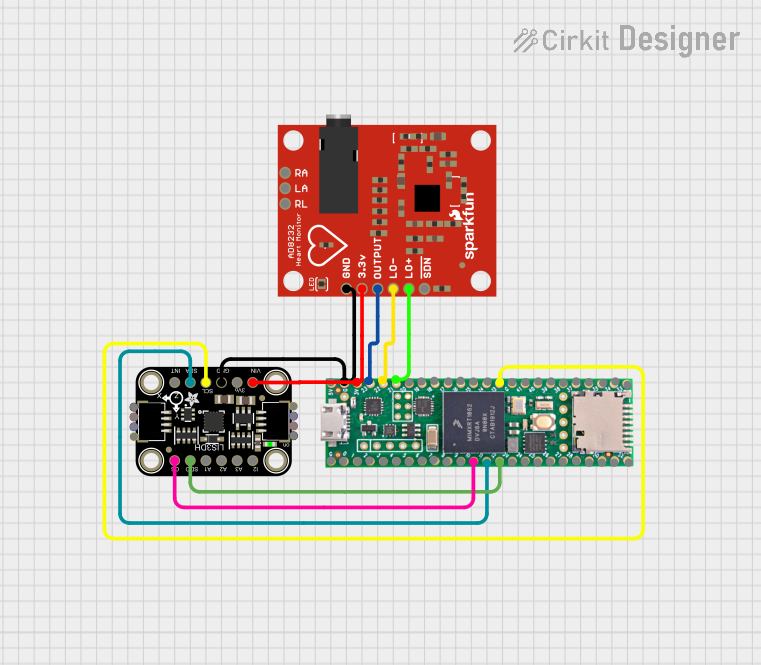
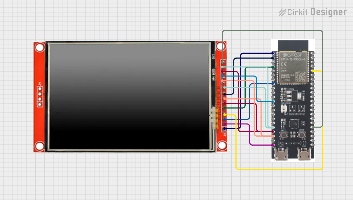
Explore Projects Built with LIS3DSH
Common Applications and Use Cases
- Motion tracking in wearable devices
- Gesture recognition in gaming controllers
- Vibration monitoring in industrial systems
- Tilt sensing in robotics and drones
- Step counting and activity monitoring in fitness devices
Technical Specifications
The LIS3DSH accelerometer is packed with features that make it suitable for a wide range of applications. Below are its key technical specifications:
| Parameter | Value |
|---|---|
| Supply Voltage (Vdd) | 1.71V to 3.6V |
| I/O Voltage (Vdd_IO) | 1.8V to 3.6V |
| Power Consumption | 2 µA in power-down mode, 11 µA in low-power mode |
| Measurement Range | ±2g, ±4g, ±6g, ±8g, ±16g (programmable) |
| Output Data Rate (ODR) | 3.125 Hz to 1.6 kHz |
| Interface | I2C (up to 400 kHz) or SPI (up to 10 MHz) |
| Operating Temperature Range | -40°C to +85°C |
| Sensitivity | 0.061 mg/LSB (±2g range) |
| Built-in Features | FIFO buffer, self-test, interrupt signals |
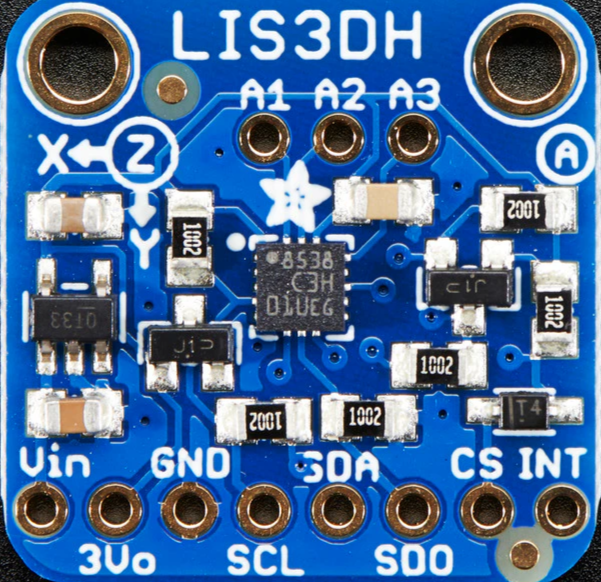
Pin Configuration and Descriptions
The LIS3DSH is typically available in a 16-pin LGA package. Below is the pinout and description:
| Pin | Name | Description |
|---|---|---|
| 1 | Vdd | Power supply (1.71V to 3.6V) |
| 2 | Vdd_IO | I/O interface voltage (1.8V to 3.6V) |
| 3 | GND | Ground |
| 4 | CS | Chip Select (SPI mode) |
| 5 | SCL/SPC | I2C Clock / SPI Serial Port Clock |
| 6 | SDA/SDI/SDO | I2C Data / SPI Data In/Out |
| 7 | INT1 | Interrupt 1 output |
| 8 | INT2 | Interrupt 2 output |
| 9-16 | NC | Not connected (reserved for future use) |
Usage Instructions
The LIS3DSH can be used in a variety of circuits, and its interface flexibility (I2C or SPI) makes it compatible with many microcontrollers, including the Arduino UNO. Below are the steps to use the LIS3DSH in a circuit:
Connecting the LIS3DSH to an Arduino UNO (I2C Mode)
- Power the Sensor: Connect the
Vddpin to the Arduino's 3.3V pin and theGNDpin to the Arduino's GND. - I2C Communication:
- Connect the
SCLpin of the LIS3DSH to the Arduino's A5 pin (I2C clock). - Connect the
SDApin of the LIS3DSH to the Arduino's A4 pin (I2C data).
- Connect the
- Pull-up Resistors: Add 4.7kΩ pull-up resistors on the
SCLandSDAlines if not already present on the breakout board. - Interrupts (Optional): Connect
INT1orINT2to any digital pin on the Arduino if you plan to use interrupts.
Sample Arduino Code
The following code demonstrates how to initialize the LIS3DSH in I2C mode and read acceleration data:
#include <Wire.h>

// LIS3DSH I2C address
#define LIS3DSH_ADDR 0x1D

// Register addresses
#define CTRL_REG4  0x20
#define OUT_X_L    0x28

void setup() {
  Wire.begin(); // Initialize I2C communication
  Serial.begin(9600); // Initialize serial communication for debugging

  // Configure LIS3DSH
  Wire.beginTransmission(LIS3DSH_ADDR);
  Wire.write(CTRL_REG4); // Select control register 4
  Wire.write(0x67); // Enable X, Y, Z axes and set ODR to 100 Hz
  Wire.endTransmission();

  Serial.println("LIS3DSH initialized.");
}

void loop() {
  int16_t x, y, z;

  // Read X-axis acceleration (low and high bytes)
  x = readAxis(OUT_X_L);
  y = readAxis(OUT_X_L + 2); // Y-axis register is 2 bytes after X
  z = readAxis(OUT_X_L + 4); // Z-axis register is 4 bytes after X

  // Print acceleration values
  Serial.print("X: "); Serial.print(x);
  Serial.print(" Y: "); Serial.print(y);
  Serial.print(" Z: "); Serial.println(z);

  delay(500); // Wait 500ms before the next reading
}

int16_t readAxis(uint8_t reg) {
  Wire.beginTransmission(LIS3DSH_ADDR);
  Wire.write(reg | 0x80); // Set MSB to enable auto-increment
  Wire.endTransmission(false);
  Wire.requestFrom(LIS3DSH_ADDR, 2);

  int16_t value = Wire.read(); // Read low byte
  value |= (Wire.read() << 8); // Read high byte and combine
  return value;
}
Important Considerations and Best Practices
- Voltage Levels: Ensure the LIS3DSH operates within its specified voltage range. Use a level shifter if interfacing with a 5V microcontroller.
- Pull-up Resistors: Always use pull-up resistors on the I2C lines if not already included on the breakout board.
- Interrupts: Configure the interrupt pins (
INT1andINT2) for advanced features like motion detection or free-fall detection. - Mounting: Securely mount the sensor to minimize noise and ensure accurate readings.
Troubleshooting and FAQs
Common Issues
No Communication with the Sensor
- Cause: Incorrect I2C address or wiring.
- Solution: Verify the I2C address (default is
0x1D) and check all connections.
Inconsistent or Noisy Readings
- Cause: Loose connections or external vibrations.
- Solution: Ensure secure connections and minimize external vibrations.
Sensor Not Responding
- Cause: Incorrect power supply voltage.
- Solution: Verify that
VddandVdd_IOare within the specified range.
FAQs
Q: Can the LIS3DSH operate in SPI mode with the Arduino UNO?
A: Yes, the LIS3DSH supports SPI communication. Connect the CS, SCL, and SDA pins to the appropriate SPI pins on the Arduino (CS, SCK, MOSI, and MISO).
Q: How do I change the measurement range?
A: Modify the CTRL_REG4 register to set the desired full-scale range (±2g, ±4g, etc.).
Q: Is the LIS3DSH suitable for battery-powered applications?
A: Yes, its low power consumption makes it ideal for battery-powered devices. Use the power-down or low-power mode to conserve energy.