Cirkit Designer Logo
Cirkit Designer
Your all-in-one circuit design IDE
Home / 
Component Documentation

How to Use TXS0108E High Speed Full Duplex Shifter 8 Way 8 Channel Logic Level Conversion Module 8-Bit 8 CH: Examples, Pinouts, and Specs

Image of TXS0108E High Speed Full Duplex Shifter 8 Way 8 Channel Logic Level Conversion Module 8-Bit 8 CH
Cirkit Designer LogoDesign with TXS0108E High Speed Full Duplex Shifter 8 Way 8 Channel Logic Level Conversion Module 8-Bit 8 CH in Cirkit Designer

Introduction

The TXS0108E is an 8-channel bidirectional logic level converter designed to enable seamless communication between devices operating at different voltage levels. Manufactured by DEVMO, this module supports high-speed, full-duplex voltage translation, making it ideal for interfacing between 1.2V to 3.6V and 1.65V to 5.5V logic levels. Its compact design and robust performance make it a popular choice for applications requiring reliable voltage level shifting.

Explore Projects Built with TXS0108E High Speed Full Duplex Shifter 8 Way 8 Channel Logic Level Conversion Module 8-Bit 8 CH

Use Cirkit Designer to design, explore, and prototype these projects online. Some projects support real-time simulation. Click "Open Project" to start designing instantly!
Wi-Fi Controlled Device Interface with Wemos D1 Mini and Logic Level Converter
Image of Toshiba AC D1 mini: A project utilizing TXS0108E High Speed Full Duplex Shifter 8 Way 8 Channel Logic Level Conversion Module 8-Bit 8 CH in a practical application
This circuit features a Wemos D1 Mini microcontroller interfaced with a Bi-Directional Logic Level Converter to facilitate communication with a 5V RX/TX module. The level converter ensures proper voltage translation between the 3.3V logic of the Wemos D1 Mini and the 5V logic of the RX/TX module.
Cirkit Designer LogoOpen Project in Cirkit Designer
Arduino Mega 2560 Controlled Motor System with I2C Communication and Hall Effect Sensing
Image of Uni1: A project utilizing TXS0108E High Speed Full Duplex Shifter 8 Way 8 Channel Logic Level Conversion Module 8-Bit 8 CH in a practical application
This is a motor control system with feedback and sensor integration. It uses an Arduino Mega 2560 to control MD03 motor drivers for DC motors, receives position and speed feedback from HEDS encoders and Hall sensors, and measures distance with SR02 ultrasonic sensors. Logic level converters ensure compatibility between different voltage levels of the components.
Cirkit Designer LogoOpen Project in Cirkit Designer
ESP32 and Logic Level Converter-Based Wi-Fi Controlled Interface
Image of Toshiba AC ESP32 devkit v1: A project utilizing TXS0108E High Speed Full Duplex Shifter 8 Way 8 Channel Logic Level Conversion Module 8-Bit 8 CH in a practical application
This circuit features an ESP32 Devkit V1 microcontroller connected to a Bi-Directional Logic Level Converter, which facilitates voltage level shifting between the ESP32 and external components. The ESP32 is powered through its VIN pin via an alligator clip cable, and the logic level converter is connected to various pins on the ESP32 to manage different voltage levels for communication.
Cirkit Designer LogoOpen Project in Cirkit Designer
Arduino UNO and Relay-Controlled RS485 Communication System
Image of Diagrama: A project utilizing TXS0108E High Speed Full Duplex Shifter 8 Way 8 Channel Logic Level Conversion Module 8-Bit 8 CH in a practical application
This circuit features an Arduino UNO microcontroller interfaced with a 4-channel relay module and a UART TTL to RS485 converter. The Arduino controls the relays via digital pins and communicates with the RS485 converter for serial communication, enabling control of external devices and communication over long distances.
Cirkit Designer LogoOpen Project in Cirkit Designer

Explore Projects Built with TXS0108E High Speed Full Duplex Shifter 8 Way 8 Channel Logic Level Conversion Module 8-Bit 8 CH

Use Cirkit Designer to design, explore, and prototype these projects online. Some projects support real-time simulation. Click "Open Project" to start designing instantly!
Image of Toshiba AC D1 mini: A project utilizing TXS0108E High Speed Full Duplex Shifter 8 Way 8 Channel Logic Level Conversion Module 8-Bit 8 CH in a practical application
Wi-Fi Controlled Device Interface with Wemos D1 Mini and Logic Level Converter
This circuit features a Wemos D1 Mini microcontroller interfaced with a Bi-Directional Logic Level Converter to facilitate communication with a 5V RX/TX module. The level converter ensures proper voltage translation between the 3.3V logic of the Wemos D1 Mini and the 5V logic of the RX/TX module.
Cirkit Designer LogoOpen Project in Cirkit Designer
Image of Uni1: A project utilizing TXS0108E High Speed Full Duplex Shifter 8 Way 8 Channel Logic Level Conversion Module 8-Bit 8 CH in a practical application
Arduino Mega 2560 Controlled Motor System with I2C Communication and Hall Effect Sensing
This is a motor control system with feedback and sensor integration. It uses an Arduino Mega 2560 to control MD03 motor drivers for DC motors, receives position and speed feedback from HEDS encoders and Hall sensors, and measures distance with SR02 ultrasonic sensors. Logic level converters ensure compatibility between different voltage levels of the components.
Cirkit Designer LogoOpen Project in Cirkit Designer
Image of Toshiba AC ESP32 devkit v1: A project utilizing TXS0108E High Speed Full Duplex Shifter 8 Way 8 Channel Logic Level Conversion Module 8-Bit 8 CH in a practical application
ESP32 and Logic Level Converter-Based Wi-Fi Controlled Interface
This circuit features an ESP32 Devkit V1 microcontroller connected to a Bi-Directional Logic Level Converter, which facilitates voltage level shifting between the ESP32 and external components. The ESP32 is powered through its VIN pin via an alligator clip cable, and the logic level converter is connected to various pins on the ESP32 to manage different voltage levels for communication.
Cirkit Designer LogoOpen Project in Cirkit Designer
Image of Diagrama: A project utilizing TXS0108E High Speed Full Duplex Shifter 8 Way 8 Channel Logic Level Conversion Module 8-Bit 8 CH in a practical application
Arduino UNO and Relay-Controlled RS485 Communication System
This circuit features an Arduino UNO microcontroller interfaced with a 4-channel relay module and a UART TTL to RS485 converter. The Arduino controls the relays via digital pins and communicates with the RS485 converter for serial communication, enabling control of external devices and communication over long distances.
Cirkit Designer LogoOpen Project in Cirkit Designer

Common Applications and Use Cases

  • Interfacing 3.3V microcontrollers (e.g., Arduino, ESP32) with 5V peripherals (e.g., sensors, displays).
  • Communication between low-voltage ICs and high-voltage systems.
  • I2C, SPI, UART, and GPIO signal level translation.
  • Mixed-voltage system designs in embedded systems, IoT devices, and robotics.

Technical Specifications

The following table outlines the key technical specifications of the TXS0108E module:

Parameter Value
Manufacturer DEVMO
Part Number TXS0108E
Voltage Range (VCCA) 1.2V to 3.6V
Voltage Range (VCCB) 1.65V to 5.5V
Channels 8 bidirectional channels
Data Rate Up to 110 Mbps (push-pull) / 1.2 Mbps (open-drain)
Operating Temperature -40°C to +85°C
Package Type Module

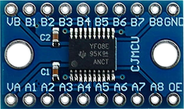
Pin Configuration and Descriptions

The TXS0108E module has 10 pins, as described in the table below:

Pin Name Direction Description
VCCA Input Voltage supply for the low-voltage side (1.2V to 3.6V).
VCCB Input Voltage supply for the high-voltage side (1.65V to 5.5V).
GND Input Ground connection (common for both voltage domains).
OE Input Output enable pin. Active HIGH. Pull LOW to disable all channels.
A1–A8 Bidirectional Low-voltage side I/O pins. Connect to the lower voltage logic signals.
B1–B8 Bidirectional High-voltage side I/O pins. Connect to the higher voltage logic signals.

Usage Instructions

How to Use the TXS0108E in a Circuit

  1. Power Supply Connections:

    • Connect the VCCA pin to the lower voltage supply (e.g., 3.3V).
    • Connect the VCCB pin to the higher voltage supply (e.g., 5V).
    • Ensure that GND is connected to the ground of both voltage domains.
  2. Enable the Module:

    • Pull the OE pin HIGH to enable the module. If not used, connect it to VCCA through a pull-up resistor.
  3. Connect Logic Signals:

    • Connect the low-voltage signals to the A1–A8 pins.
    • Connect the corresponding high-voltage signals to the B1–B8 pins.
  4. Verify Connections:

    • Ensure that the voltage levels on VCCA and VCCB are within the specified ranges.
    • Double-check the wiring to avoid short circuits or incorrect connections.

Important Considerations and Best Practices

  • Pull-Up Resistors: For open-drain communication protocols like I2C, external pull-up resistors are required on both sides of the module.
  • Signal Integrity: Keep the wiring between the module and connected devices as short as possible to minimize signal degradation.
  • Power Sequencing: Power up VCCA before VCCB to ensure proper operation.
  • Output Enable: If the module is not in use, pull the OE pin LOW to disable all channels and reduce power consumption.

Example: Connecting TXS0108E to an Arduino UNO

The following example demonstrates how to use the TXS0108E to interface a 3.3V sensor with a 5V Arduino UNO.

Circuit Diagram

  • VCCA: Connect to Arduino's 3.3V pin.
  • VCCB: Connect to Arduino's 5V pin.
  • GND: Connect to Arduino's GND.
  • OE: Connect to Arduino's 3.3V pin (or use a pull-up resistor).
  • A1: Connect to the sensor's data pin.
  • B1: Connect to Arduino's digital pin (e.g., D2).

Arduino Code Example

// Example code for reading data from a 3.3V sensor using TXS0108E
// connected to a 5V Arduino UNO.

const int sensorPin = 2; // Arduino pin connected to TXS0108E B1
int sensorValue = 0;     // Variable to store sensor data

void setup() {
  pinMode(sensorPin, INPUT); // Set sensor pin as input
  Serial.begin(9600);        // Initialize serial communication
}

void loop() {
  // Read the sensor value from the TXS0108E module
  sensorValue = digitalRead(sensorPin);

  // Print the sensor value to the Serial Monitor
  Serial.print("Sensor Value: ");
  Serial.println(sensorValue);

  delay(500); // Wait for 500ms before the next reading
}

Troubleshooting and FAQs

Common Issues and Solutions

  1. No Signal Translation:

    • Cause: The OE pin is not enabled.
    • Solution: Ensure the OE pin is pulled HIGH (connected to VCCA).
  2. Incorrect Voltage Levels:

    • Cause: Mismatched voltage supplies on VCCA and VCCB.
    • Solution: Verify that VCCA and VCCB are within the specified ranges.
  3. Signal Distortion or Noise:

    • Cause: Long wires or poor connections.
    • Solution: Use shorter wires and ensure secure connections.
  4. I2C Communication Fails:

    • Cause: Missing pull-up resistors.
    • Solution: Add appropriate pull-up resistors to the I2C lines on both sides.

FAQs

Q1: Can the TXS0108E handle analog signals?
A1: No, the TXS0108E is designed for digital logic level translation only.

Q2: What happens if I connect VCCA and VCCB to the same voltage?
A2: The module will still function, but level shifting will not occur since both sides operate at the same voltage.

Q3: Can I use the TXS0108E for SPI communication?
A3: Yes, the TXS0108E supports high-speed SPI communication, provided the data rate is within the module's specifications.

Q4: Is the TXS0108E suitable for 1.8V to 5V translation?
A4: Yes, the module supports voltage translation between 1.2V to 3.6V (VCCA) and 1.65V to 5.5V (VCCB).