
How to Use PWM DC Motor Speed Control 5-16V - : Examples, Pinouts, and Specs
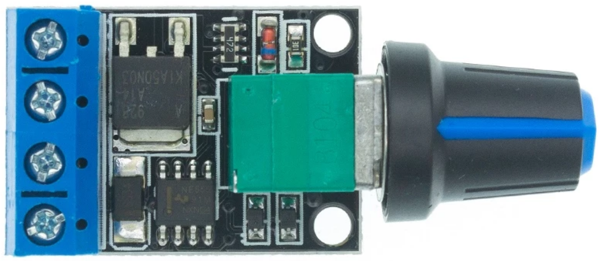
 Design with PWM DC Motor Speed Control 5-16V - in Cirkit Designer
Introduction
The PWM DC Motor Speed Control 5-16V is a compact and efficient controller designed to regulate the speed of DC motors using Pulse Width Modulation (PWM) technology. By varying the duty cycle of the PWM signal, this controller allows precise control of motor speed and torque without significant energy loss. It is ideal for applications requiring variable motor speeds, such as robotics, fans, conveyor belts, and other motor-driven systems.
Explore Projects Built with PWM DC Motor Speed Control 5-16V -
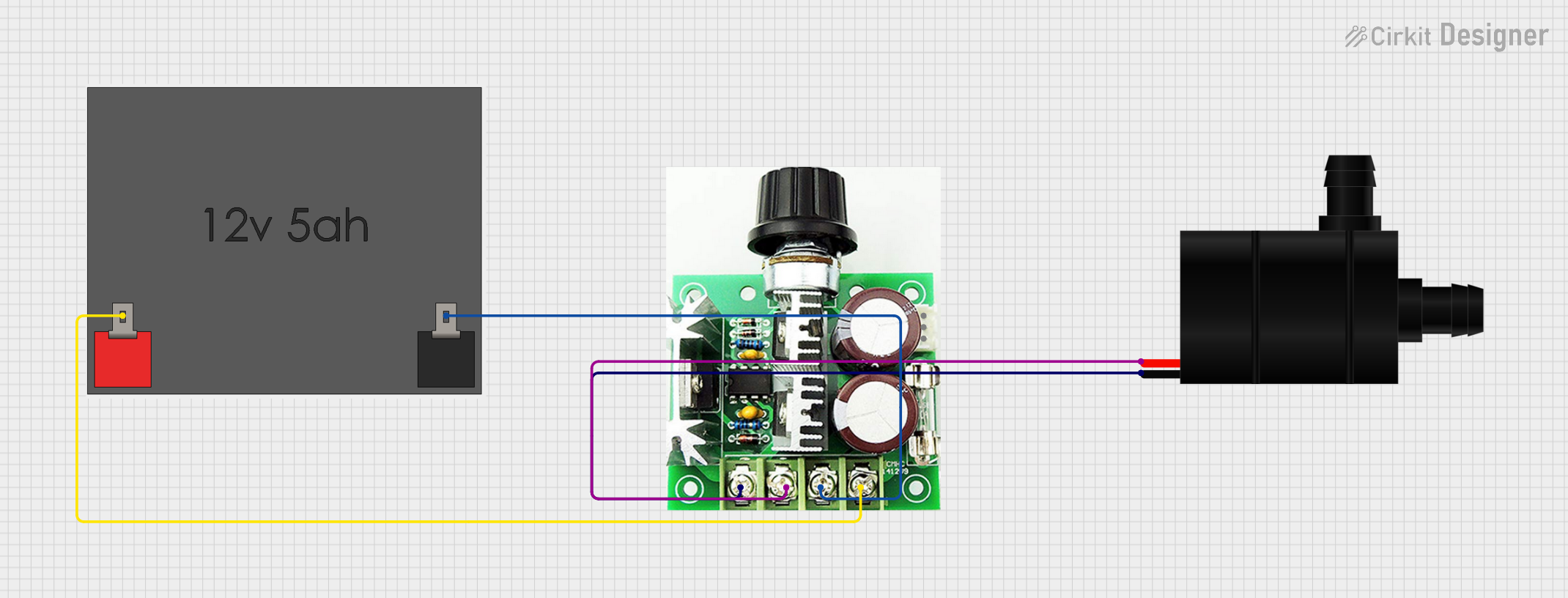 Open Project in Cirkit Designer
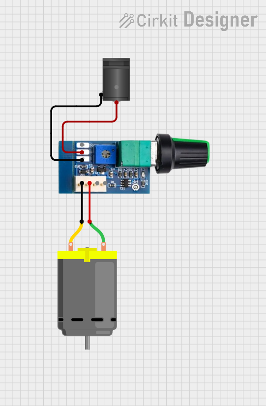 Open Project in Cirkit Designer
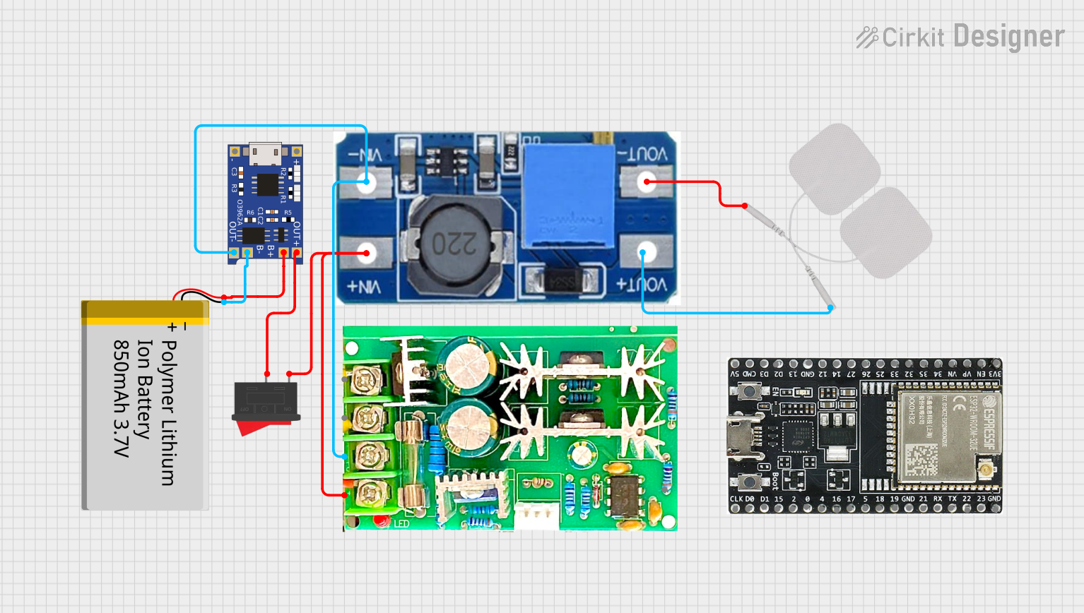 Open Project in Cirkit Designer
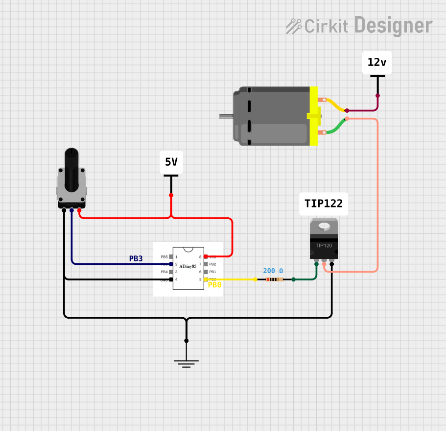 Open Project in Cirkit Designer
Explore Projects Built with PWM DC Motor Speed Control 5-16V -
Open Project in Cirkit DesignerOpen Project in Cirkit DesignerOpen Project in Cirkit DesignerOpen Project in Cirkit DesignerCommon Applications
- Robotics and automation systems
- Electric fans and blowers
- Conveyor belts and industrial machinery
- Model vehicles and hobbyist projects
- Adjustable-speed pumps and compressors
Technical Specifications
The following table outlines the key technical details of the PWM DC Motor Speed Control 5-16V:
| Parameter | Specification |
|---|---|
| Input Voltage Range | 5V to 16V DC |
| Output Current | Up to 3A (continuous) |
| PWM Frequency | 20 kHz |
| Duty Cycle Range | 0% to 100% |
| Efficiency | >90% |
| Operating Temperature | -20°C to 60°C |
| Dimensions | 50mm x 32mm x 15mm |
Pin Configuration and Descriptions
The PWM DC Motor Speed Control module typically has the following pinouts:
| Pin Name | Description |
|---|---|
| VIN+ | Positive input voltage terminal (5V to 16V DC) |
| VIN- | Negative input voltage terminal (ground) |
| MOTOR+ | Positive terminal for the DC motor |
| MOTOR- | Negative terminal for the DC motor |
| POT | Connection for the potentiometer to adjust speed |
Usage Instructions
How to Use the Component in a Circuit
- Power Supply: Connect a DC power source (5V to 16V) to the
VIN+andVIN-terminals. Ensure the power supply can provide sufficient current for the motor. - Motor Connection: Attach the DC motor to the
MOTOR+andMOTOR-terminals. Double-check the polarity to avoid reverse operation. - Speed Adjustment: Use the onboard potentiometer or an external one (if applicable) connected to the
POTpin to adjust the motor speed. Turning the potentiometer clockwise typically increases the speed, while turning it counterclockwise decreases it. - Testing: Power on the circuit and observe the motor's behavior. Adjust the potentiometer to achieve the desired speed.
Important Considerations and Best Practices
- Voltage Compatibility: Ensure the input voltage matches the motor's rated voltage to avoid damage.
- Current Rating: Verify that the motor's current draw does not exceed the controller's maximum output current (3A).
- Heat Dissipation: If operating at high currents for extended periods, consider adding a heatsink or active cooling to prevent overheating.
- Polarity Check: Always double-check the polarity of the power supply and motor connections to avoid damage to the controller or motor.
- Noise Suppression: For sensitive applications, consider adding capacitors across the motor terminals to suppress electrical noise.
Example: Connecting to an Arduino UNO
The PWM DC Motor Speed Control can be used with an Arduino UNO to automate motor speed control. Below is an example code snippet:
// Example code to control motor speed using Arduino UNO and PWM DC Motor Speed Control
// Connect Arduino PWM pin (e.g., D9) to the POT pin of the controller

const int pwmPin = 9; // PWM output pin connected to POT pin of the controller
int motorSpeed = 0;   // Variable to store motor speed (0-255)

void setup() {
  pinMode(pwmPin, OUTPUT); // Set the PWM pin as an output
}

void loop() {
  // Gradually increase motor speed from 0 to 255
  for (motorSpeed = 0; motorSpeed <= 255; motorSpeed += 5) {
    analogWrite(pwmPin, motorSpeed); // Write PWM signal to the controller
    delay(50); // Wait for 50ms before increasing speed
  }

  // Gradually decrease motor speed from 255 to 0
  for (motorSpeed = 255; motorSpeed >= 0; motorSpeed -= 5) {
    analogWrite(pwmPin, motorSpeed); // Write PWM signal to the controller
    delay(50); // Wait for 50ms before decreasing speed
  }
}
Troubleshooting and FAQs
Common Issues and Solutions
Motor Does Not Spin:
- Check the power supply voltage and ensure it is within the 5-16V range.
- Verify all connections, especially the motor and power supply terminals.
- Ensure the potentiometer is not set to the minimum position (0% duty cycle).
Motor Spins Erratically:
- Inspect the motor for mechanical issues or excessive load.
- Add capacitors (e.g., 0.1µF) across the motor terminals to reduce electrical noise.
- Ensure the power supply is stable and not fluctuating.
Controller Overheats:
- Confirm that the motor's current draw does not exceed 3A.
- Add a heatsink or active cooling to the controller if operating at high currents.
No Response to Potentiometer Adjustment:
- Check the potentiometer connection to the
POTpin. - Replace the potentiometer if it is faulty.
- Check the potentiometer connection to the
FAQs
Q: Can I use this controller with a 24V motor?
A: No, the controller is designed for a maximum input voltage of 16V. Using a 24V motor may damage the controller.
Q: Can I control the motor speed programmatically without a potentiometer?
A: Yes, you can connect a PWM signal from a microcontroller (e.g., Arduino) to the POT pin to control the speed programmatically.
Q: Is this controller suitable for brushless DC motors?
A: No, this controller is designed for brushed DC motors. Brushless motors require a dedicated ESC (Electronic Speed Controller).
Q: Can I reverse the motor direction using this controller?
A: No, this controller does not support motor direction reversal. You will need an H-bridge circuit for that functionality.