Cirkit Designer Logo
Cirkit Designer
Your all-in-one circuit design IDE
Home / 
Component Documentation

How to Use Glyph C3 : Examples, Pinouts, and Specs

Image of Glyph C3
Cirkit Designer LogoDesign with Glyph C3 in Cirkit Designer

Introduction

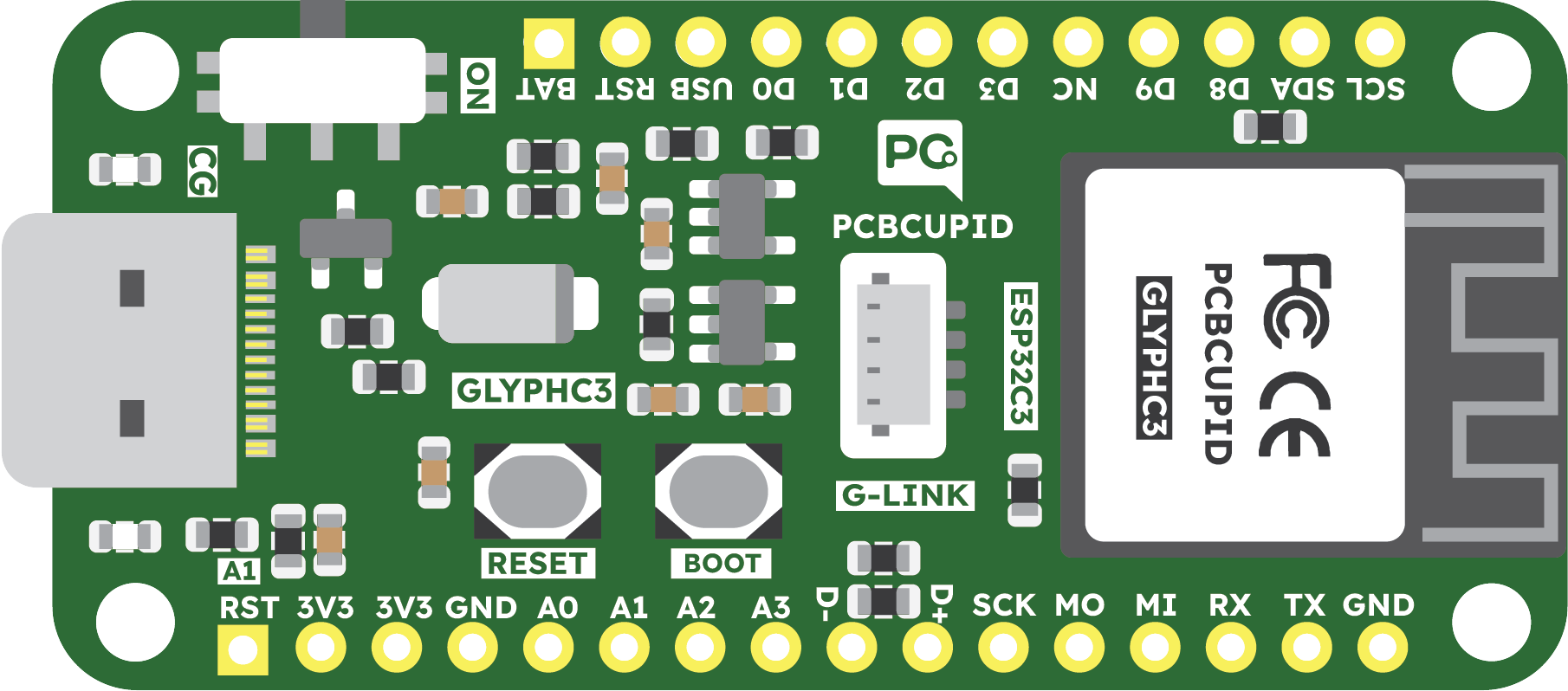
The Glyph C3 diode, manufactured by PCBCUPID with the part ID GD001, is a semiconductor device that allows current to flow in only one direction. It is a crucial component in rectifier circuits, which are used to convert alternating current (AC) to direct current (DC). This diode is commonly found in power supply units, battery charging circuits, and other electronic devices where unidirectional current flow is required.

Explore Projects Built with Glyph C3

Use Cirkit Designer to design, explore, and prototype these projects online. Some projects support real-time simulation. Click "Open Project" to start designing instantly!
Dual LED Blinker Circuit with Microcontroller Control
Image of Glyph-H2 analog: A project utilizing Glyph C3  in a practical application
This circuit consists of a Glyph C3 microcontroller connected to two red LEDs, each in series with a 220 Ohm resistor. The microcontroller's GPIO pins A1/IO1 and A3/IO2 are used to control the LEDs, while the common cathodes of the LEDs are connected to the ground (GND) of the microcontroller. This setup allows the microcontroller to turn the LEDs on and off independently by providing a voltage signal to the anodes through the resistors.
Cirkit Designer LogoOpen Project in Cirkit Designer
Glyph C3 Microcontroller with DS3231 RTC Timekeeping Circuit
Image of Glyph-C3-DS3231-I2C-Real-Time Clock Module: A project utilizing Glyph C3  in a practical application
This circuit connects a Glyph C3 microcontroller to a DS3231 Real Time Clock (RTC) module. The microcontroller provides 3.3V power and ground to the RTC, and they communicate via the I2C protocol, using the SDA and SCL lines. This setup allows the microcontroller to keep track of real-time, even when it is powered off or reset.
Cirkit Designer LogoOpen Project in Cirkit Designer
Dual RTC DS3231 Synchronization with Glyph C3 Microcontroller
Image of DS: A project utilizing Glyph C3  in a practical application
This circuit integrates two RTC DS3231 real-time clock modules with a Glyph C3 microcontroller. The RTC modules are connected to the microcontroller via I2C communication protocol, using the SCL and SDA lines for clock and data respectively. Both RTC modules and the microcontroller share a common power supply (3V3) and ground (GND), indicating that they operate at the same voltage level.
Cirkit Designer LogoOpen Project in Cirkit Designer
Arduino Nano Controlled LCD Interface with Pushbutton Inputs
Image of MacroDisplay: A project utilizing Glyph C3  in a practical application
This circuit features a Nano 3.0 ATmega328P microcontroller connected to a 16x2 I2C LCD display for output. Two pushbuttons, each with a 10k Ohm pull-down resistor, are connected to digital pins D2 and D3 of the microcontroller for input. The LCD and pushbuttons are powered by the 5V output from the microcontroller, and all components share a common ground.
Cirkit Designer LogoOpen Project in Cirkit Designer

Explore Projects Built with Glyph C3

Use Cirkit Designer to design, explore, and prototype these projects online. Some projects support real-time simulation. Click "Open Project" to start designing instantly!
Image of Glyph-H2 analog: A project utilizing Glyph C3  in a practical application
Dual LED Blinker Circuit with Microcontroller Control
This circuit consists of a Glyph C3 microcontroller connected to two red LEDs, each in series with a 220 Ohm resistor. The microcontroller's GPIO pins A1/IO1 and A3/IO2 are used to control the LEDs, while the common cathodes of the LEDs are connected to the ground (GND) of the microcontroller. This setup allows the microcontroller to turn the LEDs on and off independently by providing a voltage signal to the anodes through the resistors.
Cirkit Designer LogoOpen Project in Cirkit Designer
Image of Glyph-C3-DS3231-I2C-Real-Time Clock Module: A project utilizing Glyph C3  in a practical application
Glyph C3 Microcontroller with DS3231 RTC Timekeeping Circuit
This circuit connects a Glyph C3 microcontroller to a DS3231 Real Time Clock (RTC) module. The microcontroller provides 3.3V power and ground to the RTC, and they communicate via the I2C protocol, using the SDA and SCL lines. This setup allows the microcontroller to keep track of real-time, even when it is powered off or reset.
Cirkit Designer LogoOpen Project in Cirkit Designer
Image of DS: A project utilizing Glyph C3  in a practical application
Dual RTC DS3231 Synchronization with Glyph C3 Microcontroller
This circuit integrates two RTC DS3231 real-time clock modules with a Glyph C3 microcontroller. The RTC modules are connected to the microcontroller via I2C communication protocol, using the SCL and SDA lines for clock and data respectively. Both RTC modules and the microcontroller share a common power supply (3V3) and ground (GND), indicating that they operate at the same voltage level.
Cirkit Designer LogoOpen Project in Cirkit Designer
Image of MacroDisplay: A project utilizing Glyph C3  in a practical application
Arduino Nano Controlled LCD Interface with Pushbutton Inputs
This circuit features a Nano 3.0 ATmega328P microcontroller connected to a 16x2 I2C LCD display for output. Two pushbuttons, each with a 10k Ohm pull-down resistor, are connected to digital pins D2 and D3 of the microcontroller for input. The LCD and pushbuttons are powered by the 5V output from the microcontroller, and all components share a common ground.
Cirkit Designer LogoOpen Project in Cirkit Designer

Common Applications and Use Cases

  • Power Supply Units (PSUs)
  • AC to DC Converters
  • Battery Charging Systems
  • Voltage Clamping Circuits
  • Signal Demodulation

Technical Specifications

Key Technical Details

  • Maximum Repetitive Reverse Voltage (Vrrm): 600V
  • Maximum Continuous Forward Current (If): 3A
  • Forward Voltage Drop (Vf): 1.1V at 3A
  • Reverse Current (Ir): 5µA at 600V
  • Operating Junction Temperature (Tj): -55°C to +150°C

Pin Configuration and Descriptions

Pin Number Name Description
1 Anode The positive side of the diode, where current enters.
2 Cathode The negative side of the diode, where current exits.

Usage Instructions

How to Use the Glyph C3 in a Circuit

  1. Orientation: Ensure the diode is oriented correctly, with the anode connected to the positive voltage and the cathode to the negative side or ground.
  2. Current Rating: Do not exceed the maximum continuous forward current of 3A.
  3. Voltage Rating: Ensure the reverse voltage does not exceed 600V.
  4. Heat Management: Provide adequate heat sinking if the diode is expected to carry high currents or operate in high ambient temperatures.

Important Considerations and Best Practices

  • Reverse Polarity Protection: The Glyph C3 can be used to protect circuits from reverse polarity connections.
  • Snubber Circuits: In inductive load applications, use a snubber circuit to protect the diode from voltage spikes.
  • Flyback Diode: When used in DC motor or relay circuits, it can act as a flyback diode to prevent back EMF damage.

Troubleshooting and FAQs

Common Issues

  • Diode Not Conducting: Check for correct orientation and ensure the forward voltage is sufficient.
  • Overheating: Verify that the current and power dissipation are within the specified limits.

Solutions and Tips for Troubleshooting

  • Incorrect Orientation: Reverse the diode if it is installed backward.
  • Excessive Current: Reduce the load or use a diode with a higher current rating.
  • Thermal Issues: Improve heat dissipation with a heat sink or by increasing the PCB copper area around the diode.

FAQs

Q: Can the Glyph C3 be used for high-frequency applications? A: The Glyph C3 is suitable for low to medium frequency rectification. For high-frequency applications, a fast recovery or Schottky diode may be more appropriate.

Q: What happens if the diode is subjected to a voltage higher than 600V? A: Exceeding the maximum repetitive reverse voltage may lead to breakdown and permanent damage to the diode.

Q: Is the Glyph C3 suitable for automotive applications? A: Yes, provided the electrical specifications match the requirements of the automotive application.

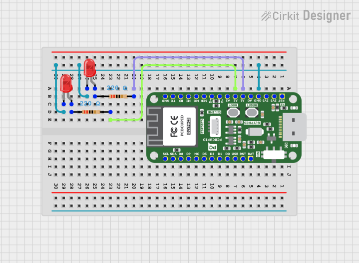
Example Connection with Arduino UNO

The following example demonstrates how to use the Glyph C3 diode to protect an Arduino UNO from reverse polarity:

// No specific code is required for the diode itself, as it is a passive component.
// However, the diode should be connected in series with the power supply.

// Connect the Anode of the Glyph C3 to the positive terminal of the power supply.
// Connect the Cathode of the Glyph C3 to the VIN pin on the Arduino UNO.

void setup() {
  // Initialize digital pin LED_BUILTIN as an output.
  pinMode(LED_BUILTIN, OUTPUT);
}

void loop() {
  // Turn the LED on (HIGH is the voltage level)
  digitalWrite(LED_BUILTIN, HIGH);
  // Wait for a second
  delay(1000);
  // Turn the LED off by making the voltage LOW
  digitalWrite(LED_BUILTIN, LOW);
  // Wait for a second
  delay(1000);
}

Note: The diode will drop the voltage by approximately 1.1V when forward biased, so ensure your power supply accounts for this voltage drop to maintain proper operating voltage for the Arduino UNO.