Cirkit Designer Logo
Cirkit Designer
Your all-in-one circuit design IDE
Home / 
Component Documentation

How to Use NFC/RFID reader PN532: Examples, Pinouts, and Specs

Image of NFC/RFID reader PN532
Cirkit Designer LogoDesign with NFC/RFID reader PN532 in Cirkit Designer

Introduction

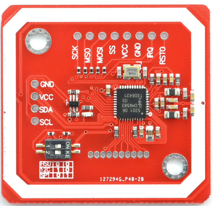
The NFC/RFID Reader PN532 is a versatile and user-friendly module capable of reading Near Field Communication (NFC) tags and Radio-Frequency Identification (RFID) cards. Manufactured by Arduino, this module is based on the PN532 v.3 chip and is widely used in applications such as access control, contactless payment systems, and data exchange between devices. Its popularity stems from its ease of use, reliability, and compatibility with a wide range of microcontrollers, including the Arduino UNO.

Explore Projects Built with NFC/RFID reader PN532

Use Cirkit Designer to design, explore, and prototype these projects online. Some projects support real-time simulation. Click "Open Project" to start designing instantly!
Biometric Access Control System with RFID and Touch Activation
Image of DOORLOCK1: A project utilizing NFC/RFID reader PN532 in a practical application
This circuit is designed for security and identification purposes, featuring an RFID-RC522 module for contactless communication and a fingerprint scanner for biometric authentication. It includes an LCD display for user interaction, a touch sensor for input, a buzzer for audio feedback, and a relay module for controlling external devices. The components are interfaced with a NANO Expansion board, which likely contains a microcontroller to coordinate the operations of the system.
Cirkit Designer LogoOpen Project in Cirkit Designer
Arduino Mega and UNO-Based NFC/RFID Reader with SD Card Data Logging
Image of nfc: A project utilizing NFC/RFID reader PN532 in a practical application
This circuit integrates an Arduino Mega 2560 and an Arduino UNO to interface with an SD card module and an NFC/RFID reader. The Arduino Mega 2560 reads analog values from various MQ sensors and logs data to the SD card, while the Arduino UNO handles communication with the NFC/RFID reader.
Cirkit Designer LogoOpen Project in Cirkit Designer
Arduino UNO RFID Access Control System with I2C LCD Feedback and Keypad Input
Image of eduVents_NFC: A project utilizing NFC/RFID reader PN532 in a practical application
This circuit is designed to read RFID tags using the RFID-RC522 module, display information on an I2C LCD screen, and accept user input via a 4x4 membrane matrix keypad. It is controlled by an Arduino UNO, which is powered by a 3xAA battery pack, and communicates with the RFID module and LCD screen using SPI and I2C protocols, respectively.
Cirkit Designer LogoOpen Project in Cirkit Designer
Arduino-Based RFID Access Control System with LCD Display
Image of ArduinoRFID_Mega: A project utilizing NFC/RFID reader PN532 in a practical application
This circuit integrates an RFID reader (RFID-RC522) and a 20x4 I2C LCD display with an Arduino 101 microcontroller. The RFID reader is used to scan RFID tags, and the scanned data is processed by the Arduino, which then displays the information on the LCD screen.
Cirkit Designer LogoOpen Project in Cirkit Designer

Explore Projects Built with NFC/RFID reader PN532

Use Cirkit Designer to design, explore, and prototype these projects online. Some projects support real-time simulation. Click "Open Project" to start designing instantly!
Image of DOORLOCK1: A project utilizing NFC/RFID reader PN532 in a practical application
Biometric Access Control System with RFID and Touch Activation
This circuit is designed for security and identification purposes, featuring an RFID-RC522 module for contactless communication and a fingerprint scanner for biometric authentication. It includes an LCD display for user interaction, a touch sensor for input, a buzzer for audio feedback, and a relay module for controlling external devices. The components are interfaced with a NANO Expansion board, which likely contains a microcontroller to coordinate the operations of the system.
Cirkit Designer LogoOpen Project in Cirkit Designer
Image of nfc: A project utilizing NFC/RFID reader PN532 in a practical application
Arduino Mega and UNO-Based NFC/RFID Reader with SD Card Data Logging
This circuit integrates an Arduino Mega 2560 and an Arduino UNO to interface with an SD card module and an NFC/RFID reader. The Arduino Mega 2560 reads analog values from various MQ sensors and logs data to the SD card, while the Arduino UNO handles communication with the NFC/RFID reader.
Cirkit Designer LogoOpen Project in Cirkit Designer
Image of eduVents_NFC: A project utilizing NFC/RFID reader PN532 in a practical application
Arduino UNO RFID Access Control System with I2C LCD Feedback and Keypad Input
This circuit is designed to read RFID tags using the RFID-RC522 module, display information on an I2C LCD screen, and accept user input via a 4x4 membrane matrix keypad. It is controlled by an Arduino UNO, which is powered by a 3xAA battery pack, and communicates with the RFID module and LCD screen using SPI and I2C protocols, respectively.
Cirkit Designer LogoOpen Project in Cirkit Designer
Image of ArduinoRFID_Mega: A project utilizing NFC/RFID reader PN532 in a practical application
Arduino-Based RFID Access Control System with LCD Display
This circuit integrates an RFID reader (RFID-RC522) and a 20x4 I2C LCD display with an Arduino 101 microcontroller. The RFID reader is used to scan RFID tags, and the scanned data is processed by the Arduino, which then displays the information on the LCD screen.
Cirkit Designer LogoOpen Project in Cirkit Designer

Technical Specifications

Key Technical Details

  • Operating Voltage: 3.3V to 5.5V
  • Operating Current (Typical): 100mA
  • Peak Current: 150mA
  • Frequency: 13.56MHz
  • Supported Protocols: ISO/IEC 14443 Type A and B, FeliCa, and the four types of NFC tags
  • Interface: I2C, SPI, and HSU (High-Speed UART)
  • Reading Distance: Up to 7cm
  • Dimensions: 43 x 40 x 4mm

Pin Configuration and Descriptions

Pin Number Name Description
1 VCC Power supply (3.3V to 5.5V)
2 GND Ground
3 SDA Serial Data (I2C interface)
4 SCL Serial Clock (I2C interface)
5 MISO Master In Slave Out (SPI interface)
6 MOSI Master Out Slave In (SPI interface)
7 SCK Serial Clock (SPI interface)
8 SS Slave Select (SPI interface)
9 RXD Receive Data (HSU interface)
10 TXD Transmit Data (HSU interface)
11 IRQ Interrupt Request (optional use)
12 RSTO Reset Output (optional use)

Usage Instructions

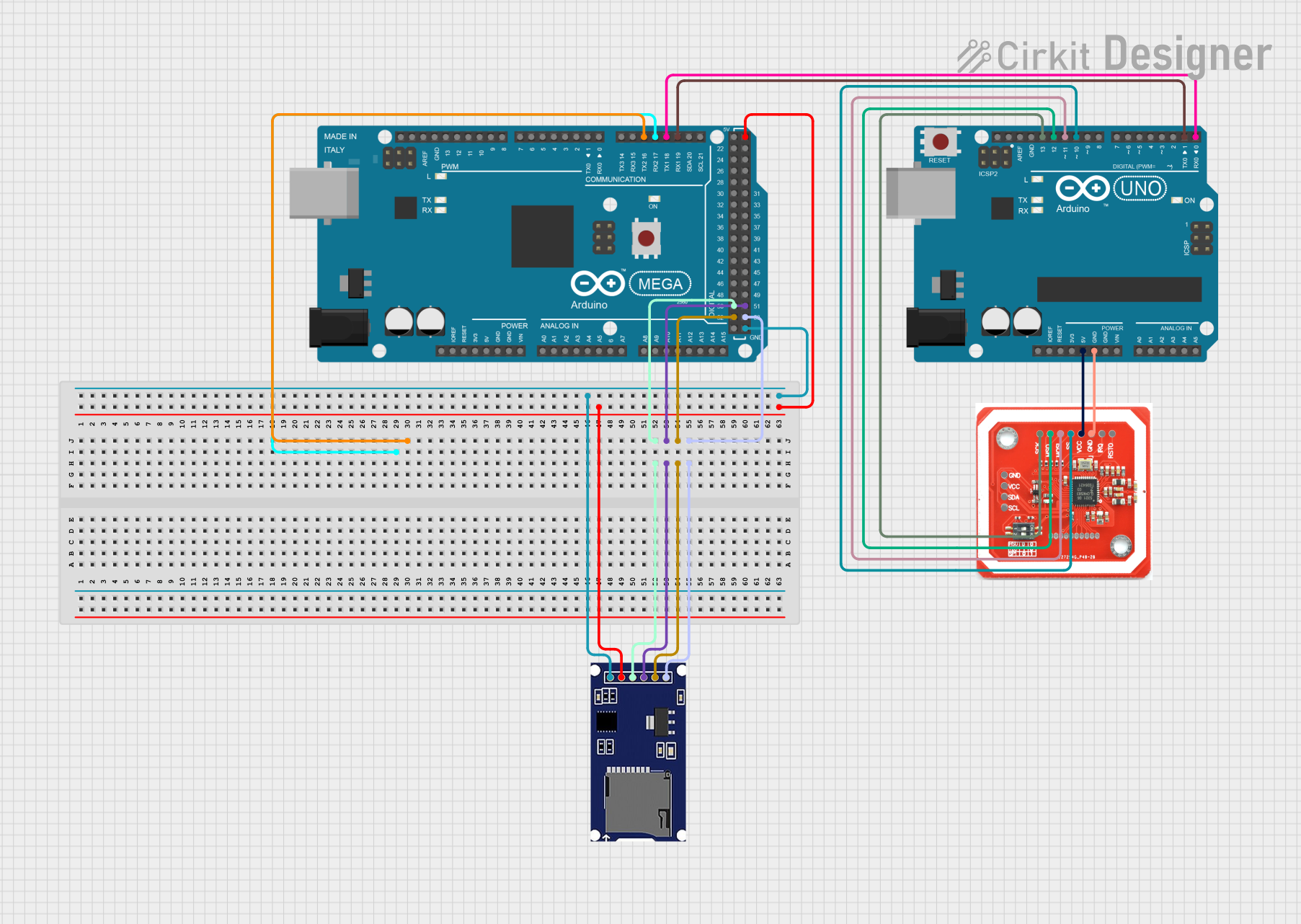
Integrating with a Circuit

To use the PN532 module with an Arduino UNO, connect the module's power pins (VCC and GND) to the Arduino's 5V and GND pins, respectively. For communication, you can choose between I2C, SPI, or HSU interfaces. I2C is recommended for simplicity and ease of use.

I2C Connection Example

  • PN532 SDA to Arduino A4 (SDA)
  • PN532 SCL to Arduino A5 (SCL)

Important Considerations and Best Practices

  • Ensure that the power supply is stable and within the specified voltage range.
  • When using I2C, you may need to use pull-up resistors on the SDA and SCL lines.
  • For SPI communication, remember to set the correct slave select (SS) pin in your code.
  • Keep the antenna area of the module clear from metallic objects to ensure optimal reading distance.

Troubleshooting and FAQs

Common Issues

  • Module Not Detected: Check wiring, ensure correct voltage supply, and verify that the correct interface (I2C/SPI/HSU) is selected in your code.
  • Poor Reading Distance: Ensure there are no metallic objects near the antenna and that the module is not subject to electrical noise.

Solutions and Tips

  • If using I2C, scan for the device address to confirm communication.
  • For SPI issues, check the continuity of the SPI lines and ensure that the SS pin is being driven correctly.
  • Reset the module if it becomes unresponsive by toggling the RSTO pin.

Example Arduino Code for I2C

#include <Wire.h>
#include <Adafruit_PN532.h>

// If using the I2C interface, define the pins for SDA and SCL
#define SDA_PIN A4
#define SCL_PIN A5

Adafruit_PN532 nfc(SDA_PIN, SCL_PIN);

void setup(void) {
  Serial.begin(115200);
  Serial.println("Hello! Scan a NFC/RFID tag to see the UID!");

  nfc.begin();
  uint32_t versiondata = nfc.getFirmwareVersion();
  if (!versiondata) {
    Serial.print("Didn't find PN53x board");
    while (1); // halt
  }
  // Configure board to read RFID tags
  nfc.SAMConfig();
}

void loop(void) {
  uint8_t success;
  uint8_t uid[] = { 0, 0, 0, 0, 0, 0, 0 }; // Buffer to store the returned UID
  uint8_t uidLength; // Length of the UID (4 or 7 bytes depending on ISO14443A card type)

  // Wait for an ISO14443A type cards (Mifare, etc.). When one is found
  // 'uid' will be populated with the UID, and uidLength will indicate
  // if it's a 4-byte or 7-byte UID
  success = nfc.readPassiveTargetID(PN532_MIFARE_ISO14443A, uid, &uidLength);

  if (success) {
    Serial.println("Found a card!");
    Serial.print("UID Length: ");Serial.print(uidLength, DEC);Serial.println(" bytes");
    Serial.print("UID Value: ");
    for (uint8_t i=0; i < uidLength; i++) {
      Serial.print(" 0x");Serial.print(uid[i], HEX);
    }
    Serial.println("");
    // Wait 1 second before continuing
    delay(1000);
  }
}

Remember to include the Adafruit PN532 library in your Arduino IDE before uploading the code to your Arduino UNO. This example demonstrates how to initialize the module, read a card's UID, and print it to the serial monitor.