How to Use LAMP - STOP INDICATOR: Examples, Pinouts, and Specs
Introduction
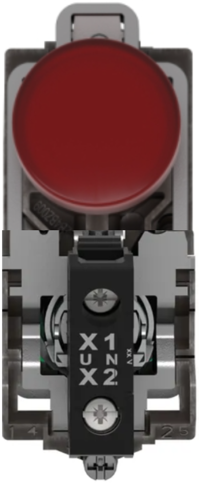
The LAMP - STOP INDICATOR (Model: XB4-BVM4), manufactured by Schneider, is a visual signaling device designed to illuminate and indicate a stop condition. It is widely used in industrial machinery, vehicles, and control panels to alert operators or drivers of a stop or emergency state. This robust and reliable component ensures clear visibility and enhances safety in various applications.
Explore Projects Built with LAMP - STOP INDICATOR

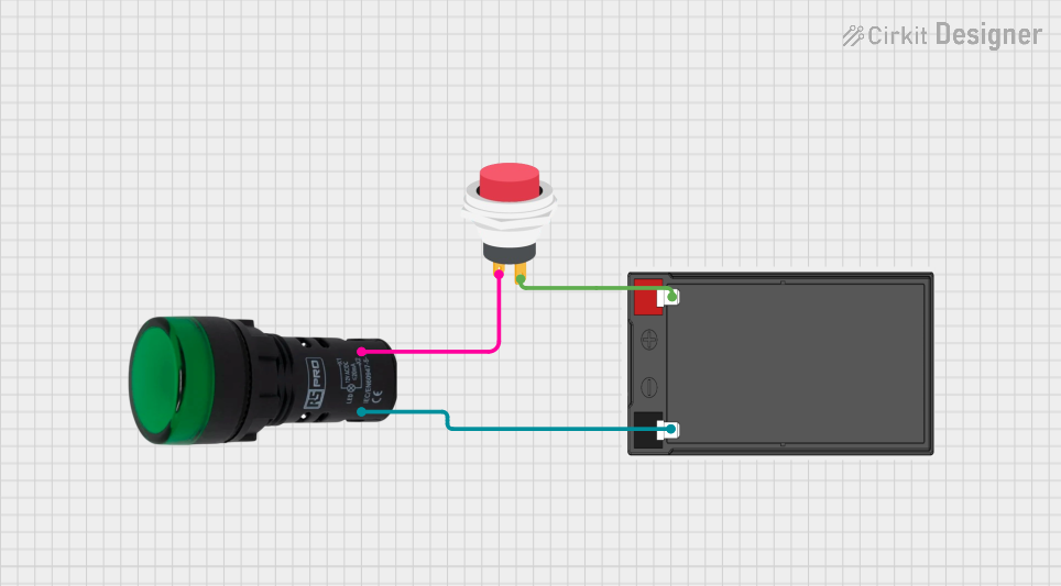
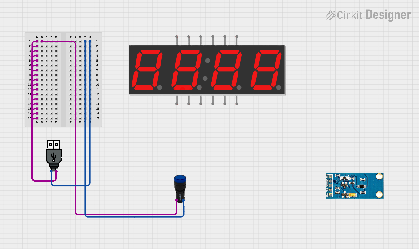
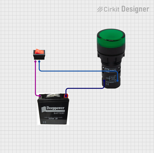
Explore Projects Built with LAMP - STOP INDICATOR
Common Applications and Use Cases
- Industrial Machinery: Indicates emergency stop conditions on control panels.
- Automotive Systems: Serves as a stop indicator in vehicles.
- Safety Systems: Alerts operators to halt operations in hazardous conditions.
- Control Panels: Provides visual feedback for stop commands in automation systems.
Technical Specifications
Below are the key technical details and pin configuration for the XB4-BVM4:
Key Technical Details
| Parameter | Specification |
|---|---|
| Manufacturer | Schneider |
| Part Number | XB4-BVM4 |
| Operating Voltage | 24V DC |
| Power Consumption | 1.2W |
| Illumination Type | LED |
| Color | Red |
| Mounting Type | Panel Mount |
| Operating Temperature | -25°C to +70°C |
| IP Rating | IP65 (Dust-tight and water-resistant) |
| Housing Material | Metal |
| Lens Material | Polycarbonate |
Pin Configuration and Descriptions
The XB4-BVM4 has a simple pin configuration for easy integration into circuits. Below is the pinout description:
| Pin Number | Pin Name | Description |
|---|---|---|
| 1 | Positive (+) | Connect to the positive terminal of the power supply. |
| 2 | Negative (-) | Connect to the negative terminal (ground). |
Usage Instructions
How to Use the Component in a Circuit
- Power Supply: Ensure a stable 24V DC power supply is available for the lamp.
- Wiring:
- Connect the Positive (+) pin to the positive terminal of the power supply.
- Connect the Negative (-) pin to the ground terminal.
- Mounting:
- Securely mount the lamp on a panel using the provided mounting hardware.
- Ensure the lens is visible and unobstructed for clear signaling.
- Testing:
- After wiring, power on the circuit to verify the lamp illuminates correctly.
- Test the stop indicator functionality in the intended application.
Important Considerations and Best Practices
- Voltage Compatibility: Ensure the power supply voltage matches the lamp's operating voltage (24V DC).
- Polarity: Double-check the polarity of the connections to avoid damage to the LED.
- Environmental Conditions: Install the lamp in environments within the specified operating temperature range and IP65 rating.
- Maintenance: Periodically inspect the lamp for dirt or damage to maintain optimal visibility.
Example: Connecting to an Arduino UNO
The XB4-BVM4 can be controlled using an Arduino UNO for automation or testing purposes. Below is an example circuit and code:
Circuit Setup
- Connect the Positive (+) pin of the lamp to a digital output pin (e.g., Pin 9) on the Arduino through a 220-ohm resistor.
- Connect the Negative (-) pin of the lamp to the Arduino's GND.
Arduino Code
// Example code to control the XB4-BVM4 Stop Indicator Lamp with Arduino UNO

const int lampPin = 9; // Pin connected to the Positive (+) terminal of the lamp

void setup() {
  pinMode(lampPin, OUTPUT); // Set the lamp pin as an output
}

void loop() {
  digitalWrite(lampPin, HIGH); // Turn the lamp ON
  delay(1000); // Keep the lamp ON for 1 second
  digitalWrite(lampPin, LOW);  // Turn the lamp OFF
  delay(1000); // Keep the lamp OFF for 1 second
}
Troubleshooting and FAQs
Common Issues and Solutions
| Issue | Possible Cause | Solution |
|---|---|---|
| Lamp does not illuminate | Incorrect wiring or loose connections | Verify wiring and ensure secure connections. |
| Lamp flickers or dims | Insufficient power supply | Check the power supply voltage and current rating. |
| Overheating | Operating outside temperature range | Ensure the environment is within -25°C to +70°C. |
| Water or dust ingress | Improper sealing or damaged housing | Verify proper mounting and inspect the IP65 seal. |
FAQs
Can the lamp operate on AC power?
- No, the XB4-BVM4 is designed for 24V DC operation only.
What is the lifespan of the LED?
- The LED has a typical lifespan of 50,000 hours under normal operating conditions.
Can the lamp be used outdoors?
- Yes, the IP65 rating ensures it is suitable for outdoor use, provided it is not submerged in water.
What resistor value should I use with an Arduino?
- A 220-ohm resistor is recommended to limit the current and protect the lamp.
By following this documentation, users can effectively integrate and maintain the XB4-BVM4 Stop Indicator Lamp in their applications.