
How to Use PLC S7-1200: Examples, Pinouts, and Specs
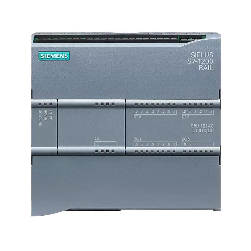
 Design with PLC S7-1200 in Cirkit Designer
Introduction
The Siemens S7-1200 (Part ID: 1) is a modular programmable logic controller (PLC) designed for automation and control applications. It is part of Siemens' SIMATIC series and is known for its compact design, integrated I/O options, and robust functionality. The S7-1200 supports various communication protocols, making it ideal for small to medium-sized automation tasks in industries such as manufacturing, process control, and building automation.
Explore Projects Built with PLC S7-1200
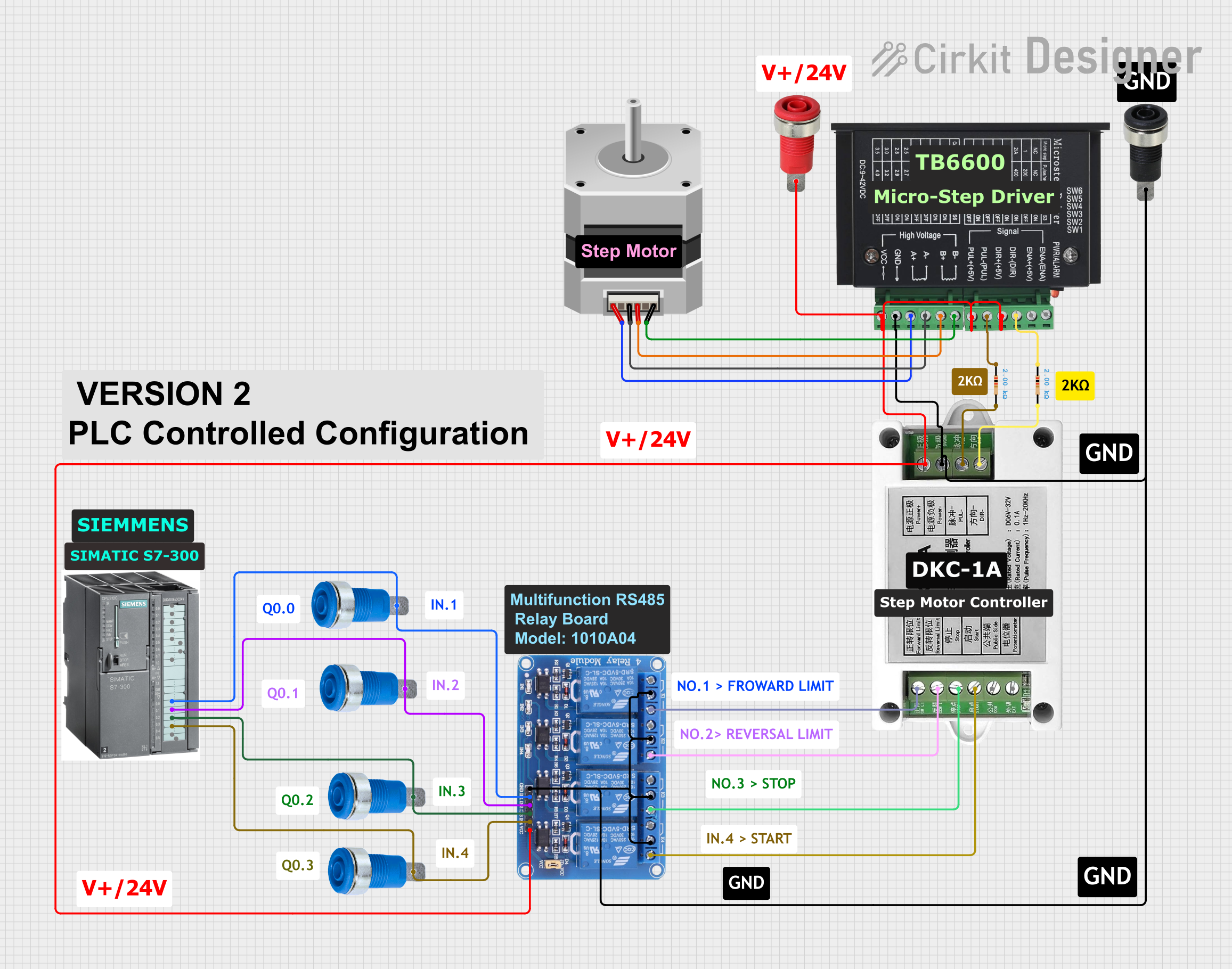 Open Project in Cirkit Designer
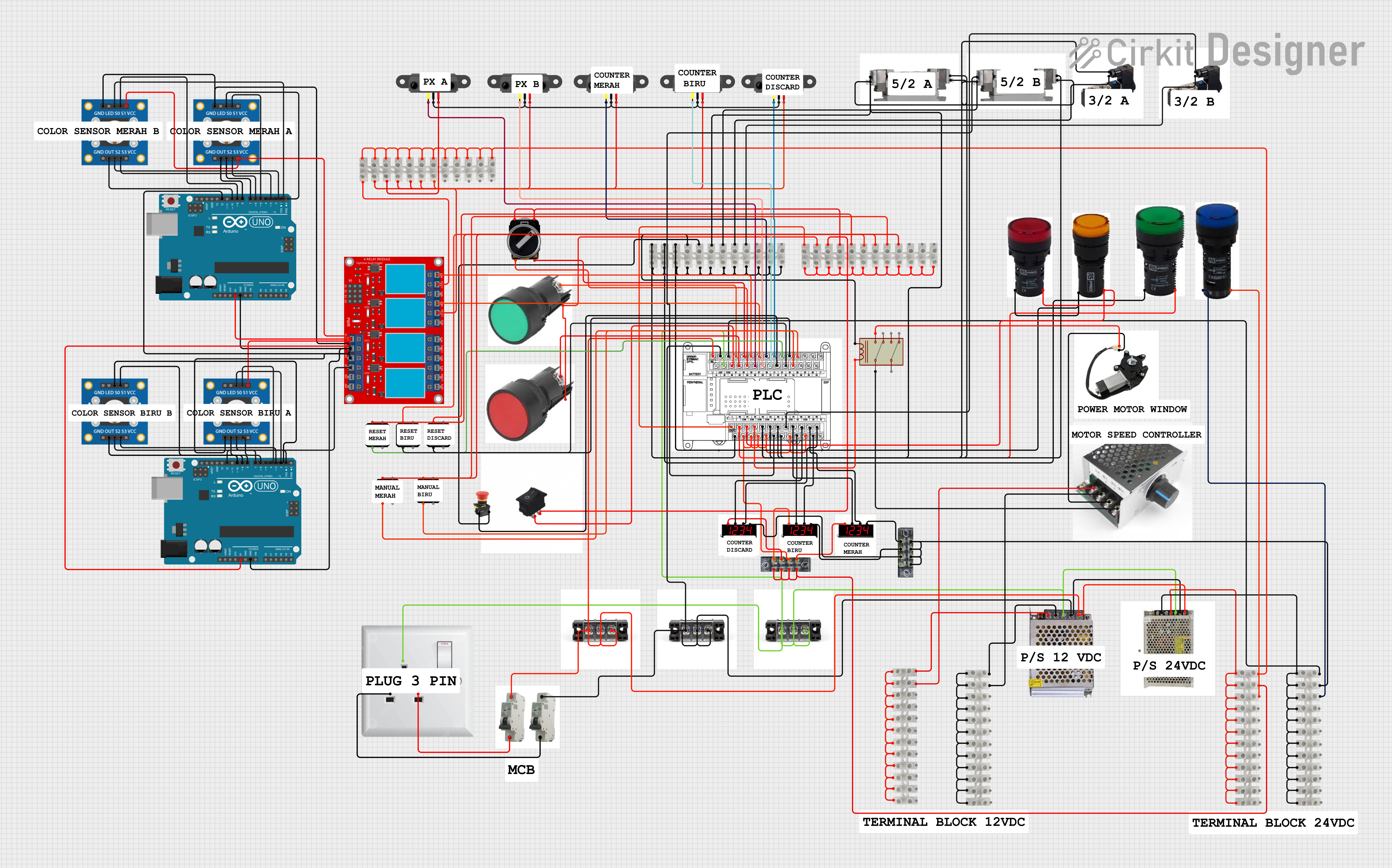 Open Project in Cirkit Designer
 Open Project in Cirkit Designer
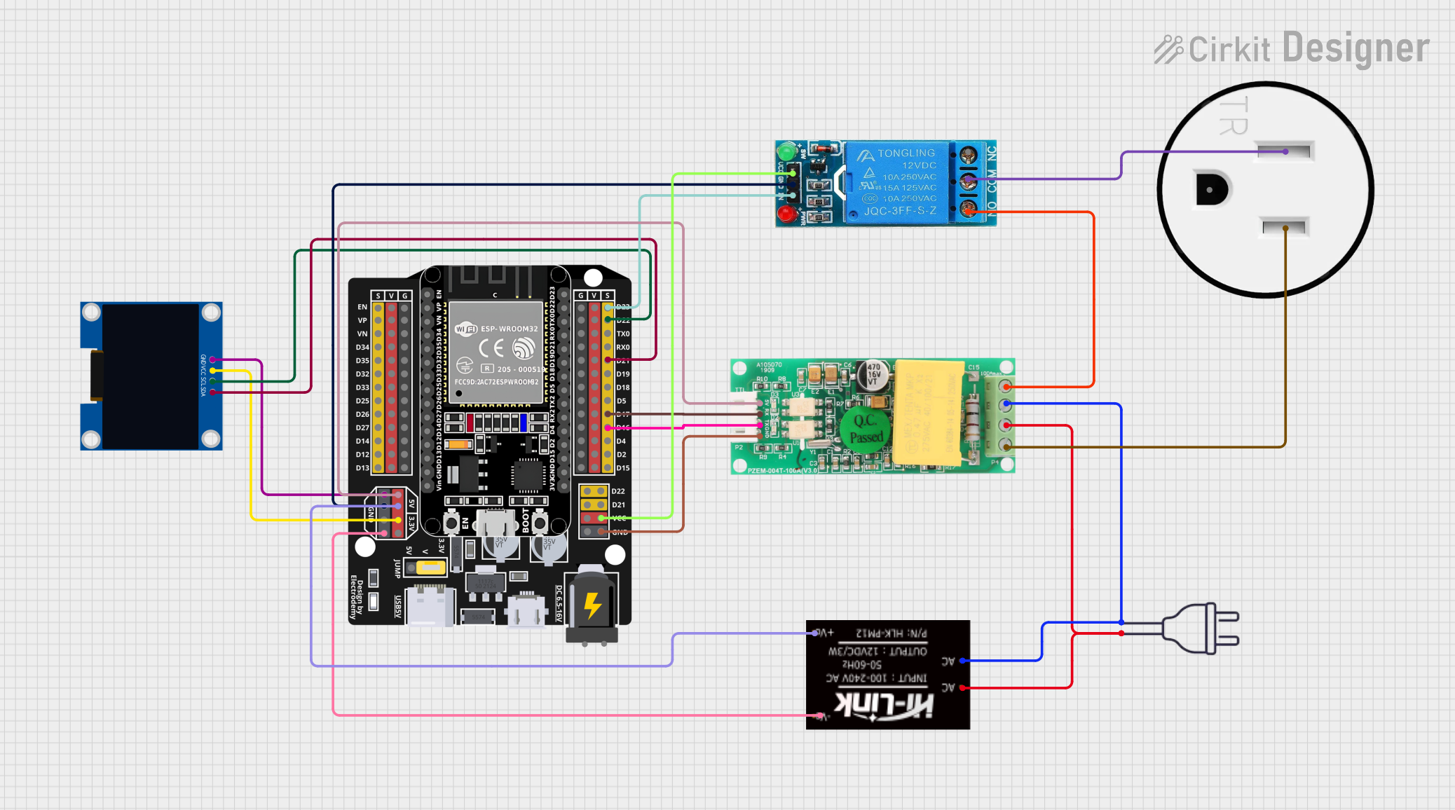 Open Project in Cirkit Designer
Explore Projects Built with PLC S7-1200
Open Project in Cirkit DesignerOpen Project in Cirkit DesignerOpen Project in Cirkit DesignerOpen Project in Cirkit DesignerCommon Applications
- Industrial automation and machine control
- Process monitoring and control
- Building management systems
- Data acquisition and communication
- Integration with SCADA and HMI systems
Technical Specifications
Key Technical Details
| Parameter | Specification |
|---|---|
| Manufacturer | Siemens |
| Part ID | 1 |
| Power Supply Voltage | 24 V DC |
| CPU Variants | CPU 1211C, CPU 1212C, CPU 1214C, CPU 1215C, CPU 1217C |
| Integrated I/O | Digital and analog inputs/outputs (varies by model) |
| Communication Protocols | PROFINET, Modbus TCP, Ethernet/IP, and optional PROFIBUS |
| Programming Software | TIA Portal (Totally Integrated Automation Portal) |
| Memory | Up to 125 KB for program and 4 MB for data (depending on CPU model) |
| Operating Temperature | -20°C to +60°C |
| Dimensions | Varies by model; compact design for DIN rail mounting |
Pin Configuration and Descriptions
The S7-1200 PLC has multiple models, each with varying I/O configurations. Below is an example pin configuration for the CPU 1212C model:
Digital Inputs
| Pin Number | Description | Voltage Range |
|---|---|---|
| 1 | DI0 (Digital Input 0) | 24 V DC |
| 2 | DI1 (Digital Input 1) | 24 V DC |
| 3 | DI2 (Digital Input 2) | 24 V DC |
| 4 | DI3 (Digital Input 3) | 24 V DC |
| 5 | DI4 (Digital Input 4) | 24 V DC |
| 6 | DI5 (Digital Input 5) | 24 V DC |
Digital Outputs
| Pin Number | Description | Voltage/Current Rating |
|---|---|---|
| 7 | DO0 (Digital Output 0) | 24 V DC / 0.5 A |
| 8 | DO1 (Digital Output 1) | 24 V DC / 0.5 A |
| 9 | DO2 (Digital Output 2) | 24 V DC / 0.5 A |
| 10 | DO3 (Digital Output 3) | 24 V DC / 0.5 A |
Power Supply and Communication
| Pin Number | Description | Voltage/Signal Type |
|---|---|---|
| 11 | +24 V (Power Supply Input) | 24 V DC |
| 12 | GND (Power Supply Ground) | Ground |
| 13 | PROFINET Port 1 (RJ45) | Ethernet Communication |
| 14 | PROFINET Port 2 (RJ45) | Ethernet Communication |
Usage Instructions
How to Use the S7-1200 in a Circuit
- Power Supply Connection: Connect a 24 V DC power supply to the power input terminals (+24 V and GND).
- I/O Wiring: Wire the digital and analog inputs/outputs as per your application requirements. Ensure proper voltage levels and current ratings.
- Communication Setup: Use the PROFINET ports for communication with other devices such as HMIs, SCADA systems, or other PLCs.
- Programming:
- Install Siemens' TIA Portal software on your computer.
- Create a new project and configure the S7-1200 PLC model.
- Write the control logic using ladder diagrams, function block diagrams, or structured text.
- Download the program to the PLC via Ethernet.
- Testing and Debugging: Use the TIA Portal's simulation and monitoring tools to test and debug your program.
Important Considerations
- Ensure the power supply voltage is stable and within the specified range (24 V DC ±10%).
- Use shielded cables for communication to minimize electromagnetic interference (EMI).
- Follow proper grounding practices to avoid electrical noise and ensure system stability.
- Regularly update the firmware of the S7-1200 to benefit from the latest features and security patches.
Example Code for S7-1200 with Arduino UNO
The S7-1200 can communicate with an Arduino UNO via Modbus TCP. Below is an example Arduino sketch for reading data from the PLC:
#include <ModbusMaster.h>

// Create an instance of the ModbusMaster library
ModbusMaster node;

void setup() {
  Serial.begin(9600); // Initialize serial communication for debugging
  node.begin(1, Serial); // Set Modbus slave ID to 1 and use Serial for communication
}

void loop() {
  uint8_t result;
  uint16_t data;

  // Read a holding register (e.g., address 40001) from the PLC
  result = node.readHoldingRegisters(0x0000, 1);

  if (result == node.ku8MBSuccess) {
    data = node.getResponseBuffer(0); // Get the data from the response buffer
    Serial.print("Data from PLC: ");
    Serial.println(data); // Print the data to the serial monitor
  } else {
    Serial.println("Failed to read from PLC"); // Print an error message if communication fails
  }

  delay(1000); // Wait for 1 second before the next read
}
Troubleshooting and FAQs
Common Issues
PLC Not Powering On
- Cause: Incorrect power supply voltage or loose connections.
- Solution: Verify the power supply voltage (24 V DC) and check all connections.
Communication Failure
- Cause: Incorrect IP configuration or faulty Ethernet cable.
- Solution: Ensure the PLC and connected devices are on the same subnet. Replace the Ethernet cable if necessary.
Program Not Executing
- Cause: PLC is in STOP mode or program errors.
- Solution: Check the PLC mode in TIA Portal and ensure the program is error-free.
I/O Not Responding
- Cause: Faulty wiring or incorrect configuration.
- Solution: Verify the wiring and ensure the I/O modules are correctly configured in TIA Portal.
FAQs
Can the S7-1200 be expanded with additional modules?
- Yes, the S7-1200 supports expansion modules for additional I/O, communication, and functionality.
What programming languages are supported?
- The S7-1200 supports ladder logic, function block diagrams, structured text, and instruction lists.
Is the S7-1200 compatible with third-party HMIs?
- Yes, the S7-1200 can communicate with third-party HMIs using standard protocols like Modbus TCP or Ethernet/IP.
How do I reset the PLC to factory settings?
- Use the TIA Portal software or the hardware reset button (if available) to reset the PLC to factory settings.
By following this documentation, users can effectively utilize the Siemens S7-1200 PLC for their automation and control needs.