How to Use Step Down Buck converter: Examples, Pinouts, and Specs
Introduction
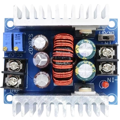
The Step Down Buck Converter (Generic, Part ID: 20A 300W) is a high-efficiency DC-DC converter designed to step down voltage from a higher input level to a lower output level. It is widely used in applications where devices require a stable, lower voltage supply from a higher voltage source. This converter is capable of handling up to 20A of current and delivering a maximum power output of 300W, making it suitable for high-power applications.
Explore Projects Built with Step Down Buck converter


Explore Projects Built with Step Down Buck converter
Common Applications and Use Cases
- Powering microcontrollers, sensors, and other low-voltage devices from a high-voltage source.
- Battery charging systems.
- Solar power systems for voltage regulation.
- Automotive electronics for stepping down car battery voltage.
- LED drivers and lighting systems.
Technical Specifications
The following table outlines the key technical details of the 20A 300W Step Down Buck Converter:
| Parameter | Value |
|---|---|
| Input Voltage Range | 6V to 40V |
| Output Voltage Range | 1.2V to 36V (adjustable) |
| Maximum Output Current | 20A (with proper cooling) |
| Maximum Power Output | 300W |
| Efficiency | Up to 95% |
| Switching Frequency | 150 kHz |
| Operating Temperature | -40°C to +85°C |
| Dimensions | 60mm x 52mm x 22mm |
Pin Configuration and Descriptions
The 20A 300W Step Down Buck Converter has the following input/output connections:
| Pin Name | Description |
|---|---|
| VIN+ | Positive input voltage terminal (connect to the higher voltage source). |
| VIN- | Negative input voltage terminal (connect to the ground of the voltage source). |
| VOUT+ | Positive output voltage terminal (connect to the load). |
| VOUT- | Negative output voltage terminal (connect to the ground of the load). |
| Adjust | Potentiometer to adjust the output voltage (clockwise to increase voltage). |
Usage Instructions
How to Use the Component in a Circuit
Connect the Input Voltage:
- Connect the positive terminal of your power source to the VIN+ pin.
- Connect the ground of your power source to the VIN- pin.
- Ensure the input voltage is within the range of 6V to 40V.
Connect the Output Load:
- Connect the positive terminal of your load to the VOUT+ pin.
- Connect the ground of your load to the VOUT- pin.
Adjust the Output Voltage:
- Use the onboard potentiometer labeled "Adjust" to set the desired output voltage.
- Turn the potentiometer clockwise to increase the output voltage and counterclockwise to decrease it.
- Use a multimeter to measure the output voltage for precise adjustment.
Cooling Considerations:
- For currents above 10A, ensure proper heat dissipation by attaching a heatsink or using active cooling (e.g., a fan).
- Avoid operating the converter at maximum current for extended periods without adequate cooling.
Power On:
- Once all connections are secure, power on the input source. The converter will regulate the output voltage as per the set value.
Important Considerations and Best Practices
- Input Voltage: Ensure the input voltage is always higher than the desired output voltage.
- Current Limitation: Do not exceed the maximum current rating of 20A to avoid damage.
- Polarity: Double-check the polarity of the input and output connections to prevent short circuits.
- Load Testing: Test the converter with a small load before connecting it to sensitive devices.
- Safety: Avoid touching the circuit while it is powered, as some components may become hot during operation.
Example: Using the Buck Converter with an Arduino UNO
The Step Down Buck Converter can be used to power an Arduino UNO from a 12V battery by stepping down the voltage to 5V. Below is an example circuit and Arduino code to blink an LED:
Circuit Connections:
- Connect the VIN+ pin of the converter to the positive terminal of the 12V battery.
- Connect the VIN- pin to the ground of the battery.
- Adjust the output voltage to 5V using the potentiometer.
- Connect the VOUT+ pin to the 5V pin of the Arduino UNO.
- Connect the VOUT- pin to the GND pin of the Arduino UNO.
Arduino Code:
// Simple LED Blink Example
// This code blinks an LED connected to pin 13 of the Arduino UNO.

void setup() {
  pinMode(13, OUTPUT); // Set pin 13 as an output pin
}

void loop() {
  digitalWrite(13, HIGH); // Turn the LED on
  delay(1000);            // Wait for 1 second
  digitalWrite(13, LOW);  // Turn the LED off
  delay(1000);            // Wait for 1 second
}
Troubleshooting and FAQs
Common Issues and Solutions
No Output Voltage:
- Cause: Incorrect input connections or insufficient input voltage.
- Solution: Verify the polarity and ensure the input voltage is within the specified range.
Output Voltage Not Adjustable:
- Cause: Faulty potentiometer or incorrect adjustment.
- Solution: Check the potentiometer for damage and adjust it slowly while monitoring the output voltage.
Overheating:
- Cause: High current draw without proper cooling.
- Solution: Attach a heatsink or use a fan to improve heat dissipation.
Load Not Powering On:
- Cause: Output voltage too low or insufficient current.
- Solution: Verify the output voltage and ensure the load's current requirements are within the converter's capacity.
FAQs
Q1: Can I use this converter to charge a 12V battery?
A1: Yes, but ensure the output voltage is set slightly higher than the battery's nominal voltage (e.g., 13.8V for a 12V lead-acid battery) and monitor the charging current.
Q2: What happens if I exceed the maximum current rating?
A2: Exceeding 20A may cause overheating, damage to the converter, or trigger the overcurrent protection (if available).
Q3: Can I use this converter with a solar panel?
A3: Yes, as long as the solar panel's output voltage is within the input range of the converter (6V to 40V).
Q4: Is the converter waterproof?
A4: No, the converter is not waterproof. Use it in a dry environment or enclose it in a waterproof case for outdoor applications.