Cirkit Designer Logo
Cirkit Designer
Your all-in-one circuit design IDE
Home / 
Component Documentation

How to Use BH1750: Examples, Pinouts, and Specs

Image of BH1750
Cirkit Designer LogoDesign with BH1750 in Cirkit Designer

Introduction

The BH1750 is a digital ambient light sensor that provides precise measurements of illuminance (light intensity) in the environment. It is capable of detecting illuminance levels ranging from 1 to 65535 lux, which makes it suitable for a wide range of applications. Commonly, the BH1750 is used in devices that require the adjustment of display backlighting or keypad lighting in response to changing light conditions, such as smartphones, tablets, digital cameras, and in various home automation systems.

Explore Projects Built with BH1750

Use Cirkit Designer to design, explore, and prototype these projects online. Some projects support real-time simulation. Click "Open Project" to start designing instantly!
Bluetooth Audio Receiver with Battery-Powered Amplifier and Loudspeakers
Image of speaker bluetooh portable: A project utilizing BH1750 in a practical application
This circuit is a Bluetooth-enabled audio system powered by a rechargeable 18650 Li-ion battery. It includes a TP4056 module for battery charging and protection, a PAM8403 amplifier with volume control to drive two loudspeakers, and a Bluetooth audio receiver to wirelessly receive audio signals.
Cirkit Designer LogoOpen Project in Cirkit Designer
ESP32-Based Smart Environmental Monitoring System with BH1750 and DHT22 Sensors
Image of 2 LD2410C BH1750 DHT22: A project utilizing BH1750 in a practical application
This circuit features an ESP32 microcontroller interfaced with a BH1750 light sensor, a DHT22 temperature and humidity sensor, and two LD2410C radar sensors. The ESP32 collects environmental data from the sensors and can communicate with the radar sensors via UART for motion detection.
Cirkit Designer LogoOpen Project in Cirkit Designer
Arduino Mega ADK Automated Plant Watering and Environmental Monitoring System
Image of Automatisierungsprojekt Mega: A project utilizing BH1750 in a practical application
This circuit features an Arduino Mega ADK as the central microcontroller, interfacing with a variety of sensors and actuators. It includes a BH1750 light sensor and a DHT11 temperature and humidity sensor for environmental monitoring, both interfacing via I2C. The system controls a stepper motor via an A4988 driver, two water pumps through a 3-channel relay, and a fan using an IRF520 PWM module, with several push switches to trigger inputs. An OLED display provides a user interface, and soil moisture levels are monitored with two soil sensors. A non-contact water level sensor is also included for liquid level detection.
Cirkit Designer LogoOpen Project in Cirkit Designer
Arduino UNO Light Sensor with BH1750 and Relay Control
Image of light: A project utilizing BH1750 in a practical application
This circuit uses an Arduino UNO to interface with a BH1750 light sensor via I2C communication. The Arduino reads light intensity data from the BH1750 sensor, which is powered by the Arduino's 3.3V and GND pins.
Cirkit Designer LogoOpen Project in Cirkit Designer

Explore Projects Built with BH1750

Use Cirkit Designer to design, explore, and prototype these projects online. Some projects support real-time simulation. Click "Open Project" to start designing instantly!
Image of speaker bluetooh portable: A project utilizing BH1750 in a practical application
Bluetooth Audio Receiver with Battery-Powered Amplifier and Loudspeakers
This circuit is a Bluetooth-enabled audio system powered by a rechargeable 18650 Li-ion battery. It includes a TP4056 module for battery charging and protection, a PAM8403 amplifier with volume control to drive two loudspeakers, and a Bluetooth audio receiver to wirelessly receive audio signals.
Cirkit Designer LogoOpen Project in Cirkit Designer
Image of 2 LD2410C BH1750 DHT22: A project utilizing BH1750 in a practical application
ESP32-Based Smart Environmental Monitoring System with BH1750 and DHT22 Sensors
This circuit features an ESP32 microcontroller interfaced with a BH1750 light sensor, a DHT22 temperature and humidity sensor, and two LD2410C radar sensors. The ESP32 collects environmental data from the sensors and can communicate with the radar sensors via UART for motion detection.
Cirkit Designer LogoOpen Project in Cirkit Designer
Image of Automatisierungsprojekt Mega: A project utilizing BH1750 in a practical application
Arduino Mega ADK Automated Plant Watering and Environmental Monitoring System
This circuit features an Arduino Mega ADK as the central microcontroller, interfacing with a variety of sensors and actuators. It includes a BH1750 light sensor and a DHT11 temperature and humidity sensor for environmental monitoring, both interfacing via I2C. The system controls a stepper motor via an A4988 driver, two water pumps through a 3-channel relay, and a fan using an IRF520 PWM module, with several push switches to trigger inputs. An OLED display provides a user interface, and soil moisture levels are monitored with two soil sensors. A non-contact water level sensor is also included for liquid level detection.
Cirkit Designer LogoOpen Project in Cirkit Designer
Image of light: A project utilizing BH1750 in a practical application
Arduino UNO Light Sensor with BH1750 and Relay Control
This circuit uses an Arduino UNO to interface with a BH1750 light sensor via I2C communication. The Arduino reads light intensity data from the BH1750 sensor, which is powered by the Arduino's 3.3V and GND pins.
Cirkit Designer LogoOpen Project in Cirkit Designer

Technical Specifications

Key Features

  • I2C bus Interface
  • Spectral responsibility is approximately human eye response
  • Illuminance to Digital Converter
  • Wide range and High resolution. (1 - 65535 lux)
  • Low Current by power down function
  • 50Hz / 60Hz Light noise reject-function
  • It is possible to select 2 types of I2C bus address
  • Adjustable measurement result for influence of optical window (It is possible to detect min. 0.11 lx, max. 100000 lx by using this function.)
  • Small measurement variation (+/- 20%)
  • The influence of infrared is very small.

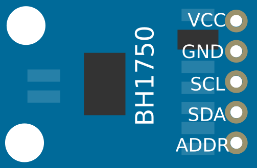
Pin Configuration and Descriptions

Pin Number Name Description
1 VCC Power supply (2.4V to 3.6V)
2 ADDR Address pin to set sensor I2C address
3 SDA I2C Data pin
4 SCL I2C Clock pin
5 GND Ground

Usage Instructions

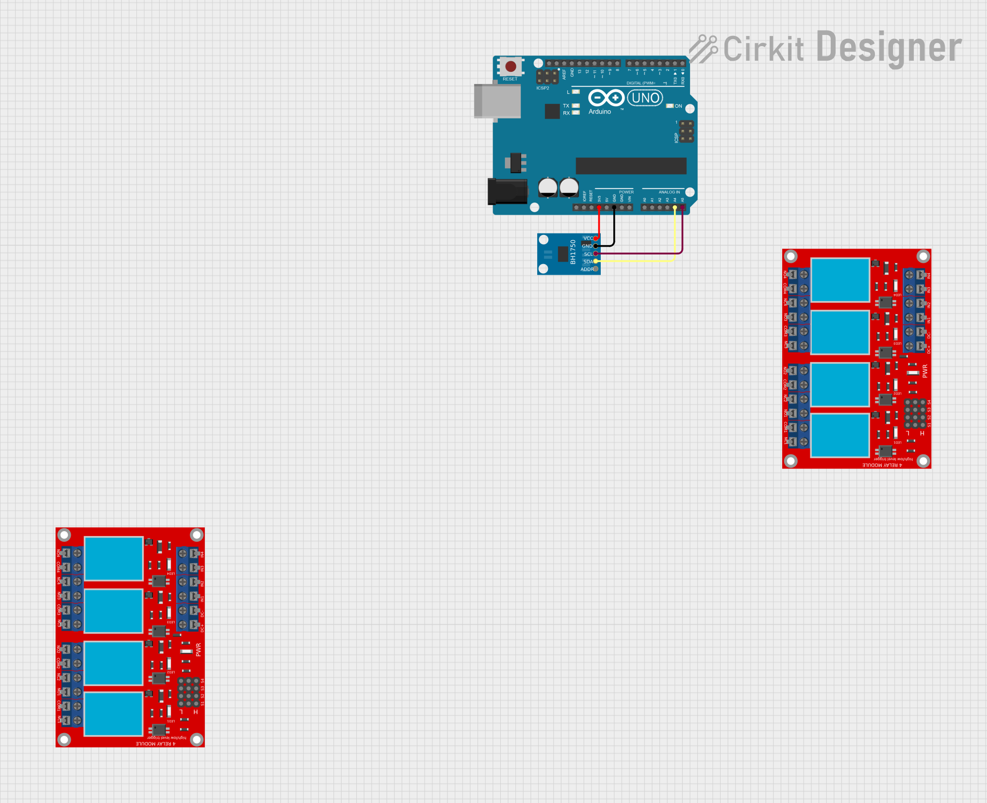
Interfacing with an Arduino UNO

To use the BH1750 with an Arduino UNO, follow these steps:

  1. Connect VCC to 3.3V on the Arduino.
  2. Connect GND to the ground on the Arduino.
  3. Connect SDA to A4 (SDA) on the Arduino.
  4. Connect SCL to A5 (SCL) on the Arduino.
  5. If the ADDR pin is left unconnected, the default I2C address is 0x23. If connected to VCC, the address is 0x5C.

Important Considerations and Best Practices

  • Ensure that the power supply is stable and within the specified voltage range.
  • Avoid exposing the sensor to direct sunlight or strong artificial light sources that could damage the sensor.
  • Use pull-up resistors with the I2C data lines if they are not already present on the Arduino board.

Sample Arduino Code

#include <Wire.h>
#include <BH1750.h>

BH1750 lightMeter;

void setup(){
  Wire.begin();
  Serial.begin(9600);

  if (lightMeter.begin(BH1750::CONTINUOUS_HIGH_RES_MODE)) {
    Serial.println(F("BH1750 Advanced begin"));
  } else {
    Serial.println(F("Error initialising BH1750"));
  }
}

void loop() {
  uint16_t lux = lightMeter.readLightLevel();
  Serial.print("Light: ");
  Serial.print(lux);
  Serial.println(" lx");
  delay(1000);
}

Troubleshooting and FAQs

Common Issues

  • Sensor Not Detected: Ensure that the I2C connections are correct and secure. Check that the correct I2C address is being used in your code.
  • Inaccurate Readings: Make sure the sensor is not placed under direct light or near strong artificial light sources. Calibrate the sensor if necessary.
  • No Data on Serial Monitor: Confirm that the correct baud rate is set in the Serial Monitor and that the Arduino board is properly connected to the computer.

Solutions and Tips for Troubleshooting

  • Always check and double-check wiring connections.
  • Use the I2C scanner sketch to confirm the sensor's address and connectivity.
  • Ensure that the Arduino libraries for the BH1750 are correctly installed and included in your sketch.
  • Reset the Arduino and power cycle the sensor if you encounter persistent issues.

FAQs

Q: Can the BH1750 be used with 5V systems? A: The BH1750 can be used with 5V systems, but a level shifter is recommended for the I2C lines, and the VCC should be connected to a 3.3V supply.

Q: How can I change the measurement mode of the BH1750? A: The measurement mode can be changed by sending the appropriate mode command to the sensor using the I2C protocol. The BH1750 library provides functions to do this easily.

Q: What is the maximum distance for the I2C connection to the BH1750? A: The maximum distance for I2C communication is typically about 1 meter, but it can vary depending on the bus capacitance and the environmental conditions. Use shorter connections for reliable communication.