How to Use Raspberry Pi Zero W: Examples, Pinouts, and Specs
Introduction
The Raspberry Pi Zero W is a compact, low-cost single-board computer equipped with built-in Wi-Fi and Bluetooth connectivity. It is designed for lightweight applications and is particularly well-suited for Internet of Things (IoT) projects, home automation, and portable computing tasks. Despite its small size, the Raspberry Pi Zero W offers impressive versatility and functionality, making it a popular choice for hobbyists, educators, and developers.
Explore Projects Built with Raspberry Pi Zero W
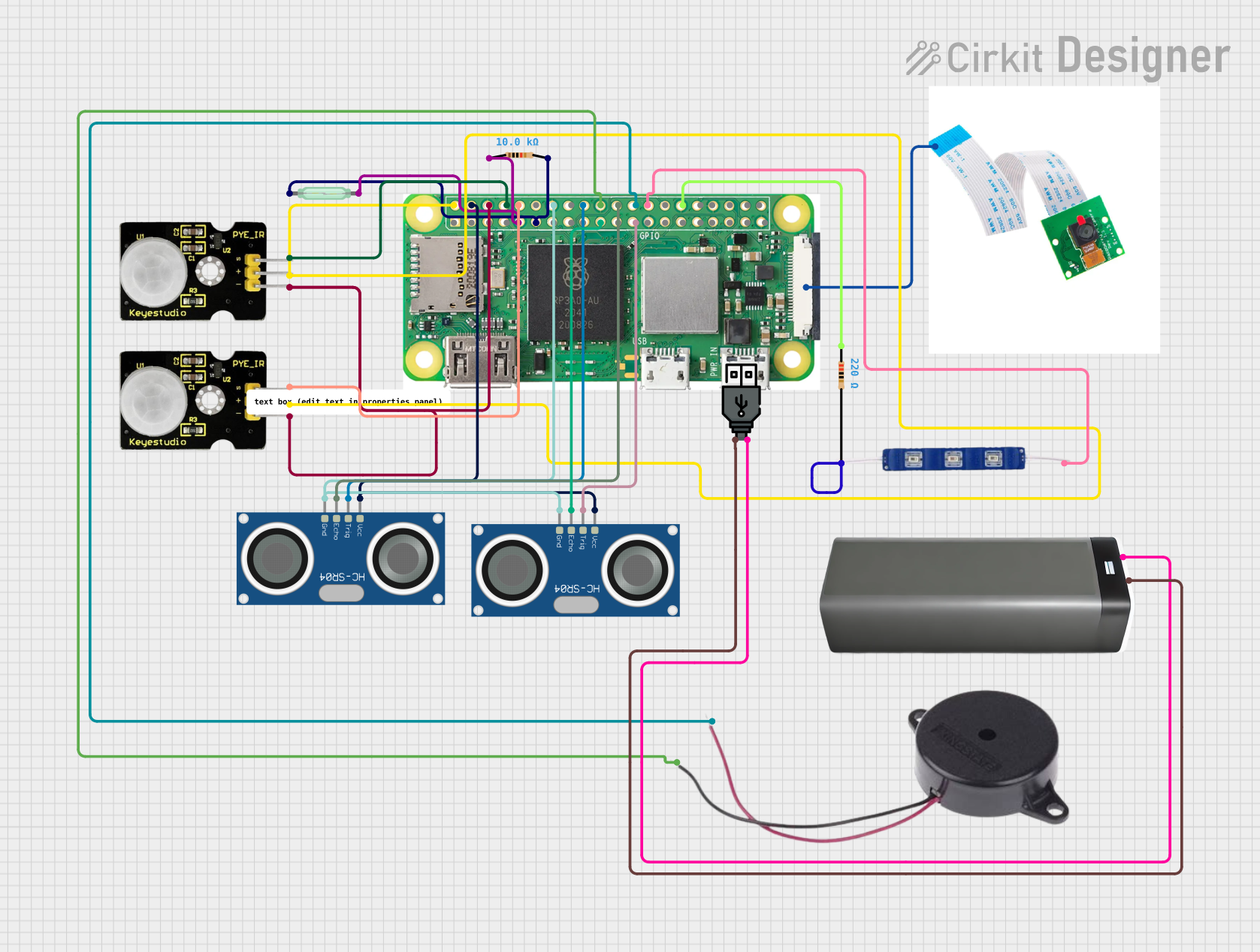
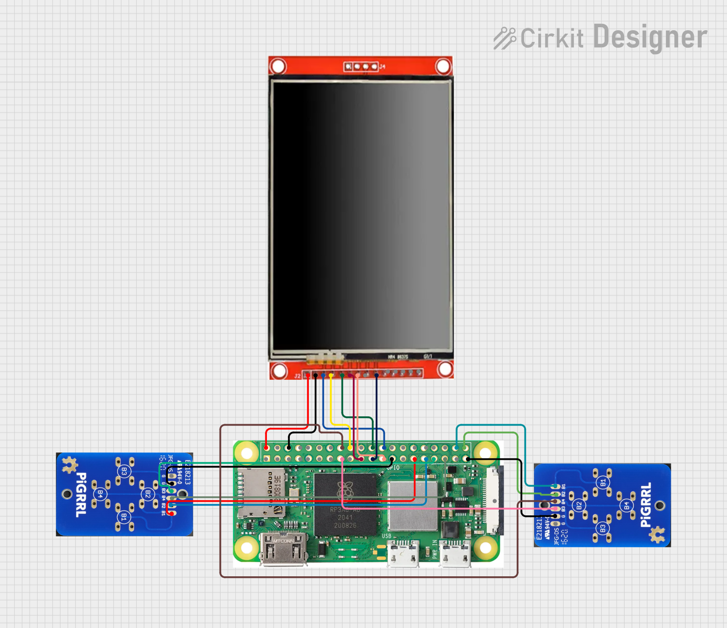
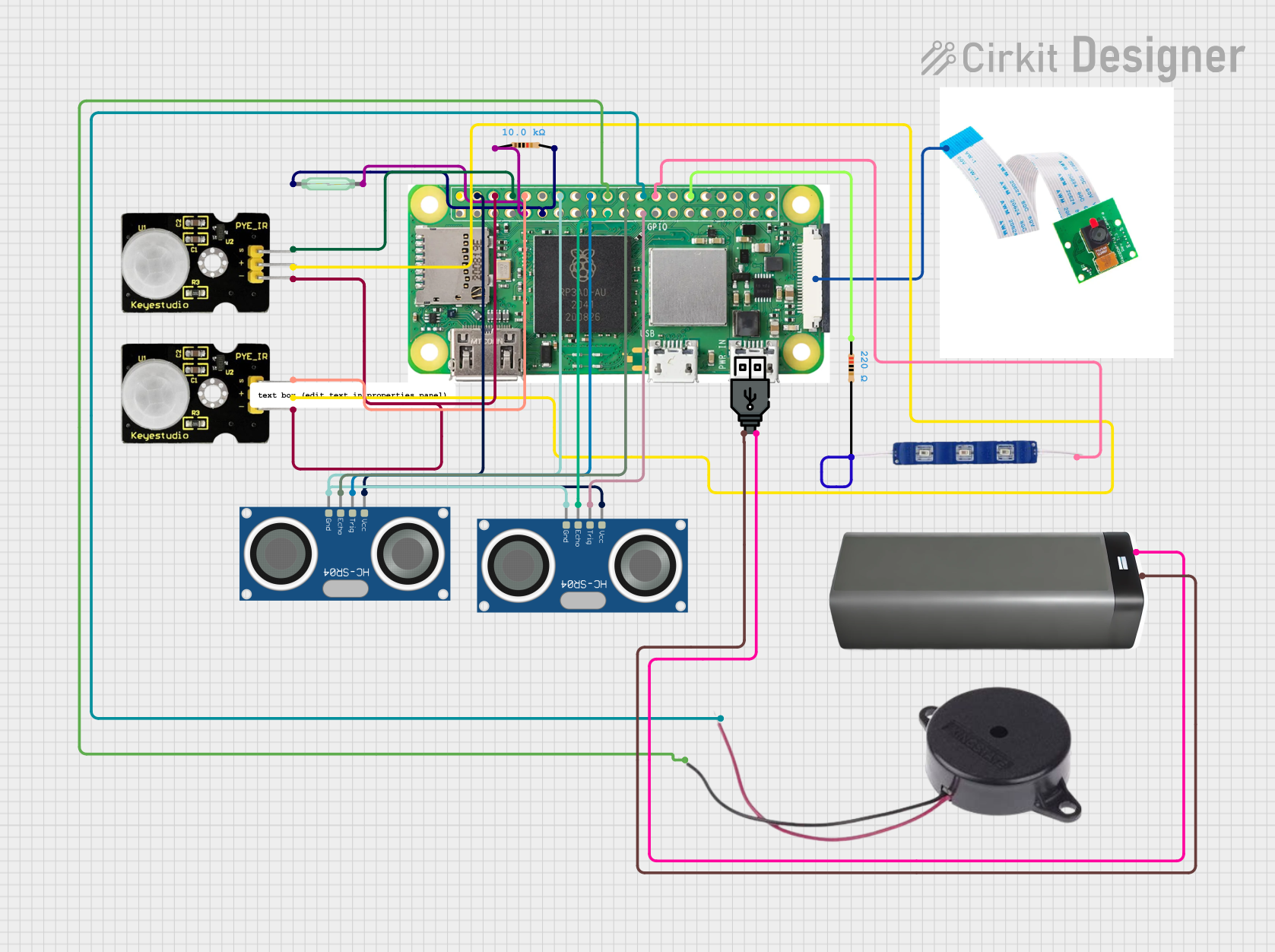

Explore Projects Built with Raspberry Pi Zero W
Common Applications and Use Cases
- IoT devices and smart home systems
- Portable media players and streaming devices
- Robotics and automation projects
- Network monitoring and security tools
- Educational tools for learning programming and electronics
- Lightweight web servers and data logging systems
Technical Specifications
The Raspberry Pi Zero W is built to deliver essential computing power in a compact form factor. Below are its key technical specifications:
General Specifications
| Feature | Specification |
|---|---|
| Processor | Broadcom BCM2835, 1GHz single-core ARM11 |
| RAM | 512MB LPDDR2 |
| Wireless Connectivity | 802.11 b/g/n Wi-Fi, Bluetooth 4.1, BLE |
| GPIO | 40-pin GPIO header (unpopulated) |
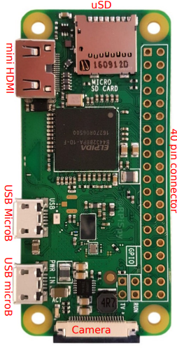
| Ports | Mini HDMI, Micro USB (power and OTG), CSI camera connector |
| Power Supply | 5V/1.2A via Micro USB |
| Dimensions | 65mm × 30mm × 5mm |
| Weight | 9g |
Pin Configuration and Descriptions
The Raspberry Pi Zero W features a 40-pin GPIO header, which is unpopulated by default. Below is the pinout for the GPIO header:
| Pin Number | Pin Name | Function |
|---|---|---|
| 1 | 3.3V Power | Power supply (3.3V) |
| 2 | 5V Power | Power supply (5V) |
| 3 | GPIO2 (SDA1) | I2C Data |
| 4 | 5V Power | Power supply (5V) |
| 5 | GPIO3 (SCL1) | I2C Clock |
| 6 | Ground | Ground |
| 7 | GPIO4 | General-purpose I/O |
| 8 | GPIO14 (TXD) | UART Transmit |
| 9 | Ground | Ground |
| 10 | GPIO15 (RXD) | UART Receive |
| ... | ... | ... |
| 39 | Ground | Ground |
| 40 | GPIO21 | General-purpose I/O |
For the full GPIO pinout, refer to the official Raspberry Pi documentation.
Usage Instructions
How to Use the Raspberry Pi Zero W in a Circuit
- Powering the Board: Use a 5V/1.2A power supply connected to the Micro USB power port. Avoid using USB ports from computers, as they may not provide sufficient current.
- Connecting Peripherals:
- Use the Mini HDMI port for video output.
- Connect USB devices (e.g., keyboard, mouse) via a Micro USB OTG adapter.
- Attach a camera module to the CSI connector if needed.
- Accessing GPIO Pins: Solder a 40-pin header to the GPIO pads for easy access to the pins. Use jumper wires to connect the GPIO pins to external components.
Important Considerations and Best Practices
- Heat Management: While the Raspberry Pi Zero W is energy-efficient, prolonged use under heavy loads may cause it to heat up. Consider using a heatsink for better thermal management.
- Wi-Fi Signal Strength: Ensure the board is placed in an area with good Wi-Fi coverage for optimal performance.
- Static Protection: Handle the board with care to avoid damage from electrostatic discharge (ESD). Use an anti-static wrist strap if possible.
- Software Setup: Install the Raspberry Pi OS on a microSD card (minimum 8GB recommended) and insert it into the microSD card slot. Configure the OS using the Raspberry Pi Imager tool.
Example: Connecting to an Arduino UNO
The Raspberry Pi Zero W can communicate with an Arduino UNO via serial communication. Below is an example Python script to send data from the Raspberry Pi to the Arduino:
import serial
import time
Initialize serial communication with the Arduino
Replace '/dev/ttyUSB0' with the correct port for your setup
arduino = serial.Serial('/dev/ttyUSB0', 9600, timeout=1) time.sleep(2) # Wait for the connection to initialize
Send data to the Arduino
while True: arduino.write(b'Hello, Arduino!\n') # Send a message print("Message sent to Arduino") time.sleep(1) # Wait 1 second before sending the next message
**Note**: Ensure the Arduino is configured to receive serial data at the same baud rate (9600 in this example).
Troubleshooting and FAQs
Common Issues and Solutions
The Raspberry Pi Zero W does not boot:
- Ensure the microSD card is properly inserted and contains a valid Raspberry Pi OS image.
- Verify that the power supply provides sufficient current (5V/1.2A).
- Check for any visible damage to the board or connectors.
Wi-Fi connectivity issues:
- Confirm that the Wi-Fi credentials are correctly configured in the OS.
- Place the board closer to the Wi-Fi router to improve signal strength.
- Update the Raspberry Pi OS to ensure compatibility with your network.
GPIO pins not working:
- Double-check the pin connections and ensure the correct GPIO pins are being used.
- Verify that the GPIO pins are not damaged or shorted.
- Use the
gpio readallcommand (via terminal) to check the pin states.
FAQs
Can I power the Raspberry Pi Zero W via GPIO pins? Yes, you can power the board by supplying 5V to the 5V pin and connecting ground to a GND pin. However, this bypasses the onboard power protection circuitry, so proceed with caution.
What is the maximum current output of the GPIO pins? Each GPIO pin can source/sink up to 16mA, with a total maximum current of 50mA across all GPIO pins.
Can I use the Raspberry Pi Zero W without soldering? Yes, you can use solderless GPIO headers or breakout boards to access the GPIO pins without soldering.
By following this documentation, you can effectively utilize the Raspberry Pi Zero W for a wide range of projects and applications.