How to Use Step Up Boost Power Converter, Adjustable Voltage Regulator: Examples, Pinouts, and Specs
Introduction
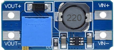
The Youmile Step Up Boost Power Converter is a versatile and efficient adjustable voltage regulator designed to step up a lower input voltage to a higher, stable output voltage. This component is widely used in applications requiring a consistent power supply, such as battery-powered devices, portable electronics, and DIY projects. Its compact design and adjustable output make it ideal for hobbyists and professionals alike.
Explore Projects Built with Step Up Boost Power Converter, Adjustable Voltage Regulator


Explore Projects Built with Step Up Boost Power Converter, Adjustable Voltage Regulator
Common Applications and Use Cases
- Powering devices requiring a higher voltage than the input source (e.g., 5V to 12V).
- Battery-powered systems, such as lithium-ion or AA battery packs.
- DIY electronics projects, including Arduino-based systems.
- LED lighting systems and small motor drivers.
- Emergency power supplies and portable chargers.
Technical Specifications
Key Technical Details
- Input Voltage Range: 3V to 32V DC
- Output Voltage Range: 5V to 35V DC (adjustable via potentiometer)
- Maximum Output Current: 4A (with proper heat dissipation)
- Efficiency: Up to 92% (depending on input/output voltage and load)
- Switching Frequency: 150 kHz
- Operating Temperature: -40°C to +85°C
- Dimensions: Approximately 43mm x 21mm x 14mm
Pin Configuration and Descriptions
| Pin Name | Description |
|---|---|
| VIN+ | Positive input voltage terminal (connect to the positive side of the power source). |
| VIN- | Negative input voltage terminal (connect to the ground of the power source). |
| VOUT+ | Positive output voltage terminal (connect to the positive side of the load). |
| VOUT- | Negative output voltage terminal (connect to the ground of the load). |
Usage Instructions
How to Use the Component in a Circuit
- Connect the Input Voltage:
- Attach the positive terminal of your power source to the
VIN+pin. - Connect the ground of your power source to the
VIN-pin.
- Attach the positive terminal of your power source to the
- Connect the Output Load:
- Attach the positive terminal of your load to the
VOUT+pin. - Connect the ground of your load to the
VOUT-pin.
- Attach the positive terminal of your load to the
- Adjust the Output Voltage:
- Use a small screwdriver to turn the onboard potentiometer.
- Turn clockwise to increase the output voltage or counterclockwise to decrease it.
- Measure the output voltage with a multimeter to ensure it matches your desired value.
- Power On:
- Once all connections are secure, power on the input source. The module will step up the input voltage to the configured output voltage.
Important Considerations and Best Practices
- Heat Dissipation: For currents above 2A, ensure proper heat dissipation by attaching a heatsink or using active cooling.
- Input Voltage: The input voltage must always be lower than the desired output voltage.
- Polarity: Double-check the polarity of your connections to avoid damaging the module.
- Load Testing: Before connecting sensitive devices, test the output voltage and current with a dummy load.
- Arduino Compatibility: This module can be used to power Arduino projects requiring higher voltages. Below is an example of using the module with an Arduino UNO.
Example Code for Arduino UNO
// Example: Using the Step Up Boost Converter to power an Arduino UNO
// This code demonstrates reading a sensor powered by the boost converter.

// Define the analog pin connected to the sensor
const int sensorPin = A0;

void setup() {
  Serial.begin(9600); // Initialize serial communication at 9600 baud
  pinMode(sensorPin, INPUT); // Set the sensor pin as input
}

void loop() {
  int sensorValue = analogRead(sensorPin); // Read the sensor value
  float voltage = sensorValue * (5.0 / 1023.0); // Convert to voltage
  Serial.print("Sensor Voltage: ");
  Serial.print(voltage);
  Serial.println(" V");
  delay(1000); // Wait for 1 second before the next reading
}
Note: Ensure the boost converter is configured to provide the correct voltage for your Arduino UNO and connected peripherals.
Troubleshooting and FAQs
Common Issues and Solutions
No Output Voltage:
- Verify that the input voltage is within the specified range (3V to 32V).
- Check all connections for proper polarity and secure contact.
- Ensure the potentiometer is not turned all the way down.
Overheating:
- Reduce the load current or improve heat dissipation with a heatsink or fan.
- Ensure the input voltage is not too close to the output voltage, as this reduces efficiency.
Fluctuating Output Voltage:
- Check for loose connections or poor solder joints.
- Ensure the input power source is stable and capable of supplying sufficient current.
Output Voltage Not Adjustable:
- Verify that the potentiometer is functional and not damaged.
- Ensure the input voltage is lower than the desired output voltage.
FAQs
Can I use this module to charge batteries?
- Yes, but ensure the output voltage is set to the appropriate charging voltage for your battery type, and use a current-limiting circuit if necessary.
What happens if I reverse the input polarity?
- The module does not have built-in reverse polarity protection. Reversing the input polarity may permanently damage the module.
Can I use this module with a solar panel?
- Yes, as long as the solar panel's output voltage and current are within the module's input range.
Is it safe to use this module without a heatsink?
- For currents below 2A, a heatsink is generally not required. For higher currents, a heatsink or active cooling is recommended to prevent overheating.
By following this documentation, you can effectively integrate the Youmile Step Up Boost Power Converter into your projects and ensure reliable performance.