How to Use cd4017: Examples, Pinouts, and Specs
Introduction
The CD4017 is a decade counter integrated circuit (IC) that counts from 0 to 10 and provides ten output signals, each corresponding to a count. It is a versatile and widely used IC in digital electronics, particularly in applications requiring sequential counting or output control. The CD4017 is commonly employed in LED chasers, frequency dividers, event counters, and other timing-related circuits.
Explore Projects Built with cd4017


Explore Projects Built with cd4017
Common Applications
- LED chasers and sequencers
- Frequency division circuits
- Event counters
- Light animations and displays
- Signal multiplexing
Technical Specifications
The CD4017 is a CMOS-based IC, making it highly efficient and suitable for low-power applications. Below are its key technical details:
| Parameter | Value |
|---|---|
| Supply Voltage (Vdd) | 3V to 15V |
| Maximum Output Current | 10mA |
| Maximum Clock Frequency | 5 MHz (at 10V supply) |
| Power Dissipation | 500mW |
| Operating Temperature | -40°C to +85°C |
| Package Types | DIP-16, SOIC-16 |
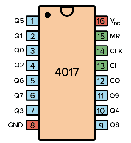
Pin Configuration and Descriptions
The CD4017 has 16 pins, each serving a specific function. Below is the pinout and description:
| Pin Number | Pin Name | Description |
|---|---|---|
| 1 | Q0 | Output 0 (first output in the sequence) |
| 2 | Q1 | Output 1 |
| 3 | Q2 | Output 2 |
| 4 | Q3 | Output 3 |
| 5 | Q4 | Output 4 |
| 6 | Q5 | Output 5 |
| 7 | Q6 | Output 6 |
| 8 | GND | Ground (0V reference) |
| 9 | Q7 | Output 7 |
| 10 | Q8 | Output 8 |
| 11 | Q9 | Output 9 (last output in the sequence) |
| 12 | Carry Out (CO) | Outputs a pulse after every 10 clock pulses (used for cascading multiple ICs) |
| 13 | Clock Enable | Enables or disables the clock input (active LOW) |
| 14 | Clock (CLK) | Clock input signal (triggers the counter) |
| 15 | Reset | Resets the counter to 0 (active HIGH) |
| 16 | Vdd | Positive supply voltage |
Usage Instructions
The CD4017 is straightforward to use in a circuit. Below are the steps and considerations for its proper operation:
Basic Circuit Setup
- Power Supply: Connect pin 16 (Vdd) to the positive supply voltage (3V to 15V) and pin 8 (GND) to ground.
- Clock Input: Provide a clock signal to pin 14 (CLK). This can be generated using a 555 timer IC, an Arduino, or any other clock source.
- Outputs: Connect the desired outputs (Q0 to Q9) to your load (e.g., LEDs with current-limiting resistors).
- Reset: If a reset function is required, connect pin 15 to a push button or control circuit. When pin 15 is HIGH, the counter resets to 0.
- Clock Enable: If you want to enable or disable the clock, use pin 13. When pin 13 is LOW, the clock is enabled; when HIGH, the clock is disabled.
Example: LED Chaser Circuit with Arduino UNO
The following example demonstrates how to use the CD4017 with an Arduino UNO to create an LED chaser:
Circuit Connections
- Connect pin 16 (Vdd) to 5V and pin 8 (GND) to ground.
- Connect pin 14 (CLK) to Arduino digital pin 2.
- Connect LEDs to outputs Q0 to Q9 (pins 1, 2, 3, 4, 5, 6, 7, 9, 10, 11) with 220-ohm resistors in series.
- Leave pin 13 (Clock Enable) and pin 15 (Reset) unconnected for continuous operation.
Arduino Code
// CD4017 LED Chaser Example
// This code generates a clock signal for the CD4017 decade counter
// to create a sequential LED chaser effect.

#define CLOCK_PIN 2  // Arduino pin connected to CD4017 clock input

void setup() {
  pinMode(CLOCK_PIN, OUTPUT);  // Set CLOCK_PIN as an output
}

void loop() {
  digitalWrite(CLOCK_PIN, HIGH);  // Generate a HIGH pulse
  delay(100);                     // Wait for 100ms (adjust for speed)
  digitalWrite(CLOCK_PIN, LOW);   // Generate a LOW pulse
  delay(100);                     // Wait for 100ms
}
Best Practices
- Use decoupling capacitors (e.g., 0.1µF) across the power supply pins (Vdd and GND) to reduce noise.
- Avoid exceeding the maximum voltage and current ratings to prevent damage to the IC.
- If cascading multiple CD4017 ICs, connect the Carry Out (pin 12) of the first IC to the Clock (pin 14) of the next IC.
Troubleshooting and FAQs
Common Issues
No Output on Pins Q0 to Q9:
- Ensure the clock signal is being provided to pin 14.
- Verify that pin 13 (Clock Enable) is LOW.
- Check the power supply connections (Vdd and GND).
Outputs Not Changing:
- Confirm that the clock signal is toggling between HIGH and LOW.
- Check if pin 15 (Reset) is stuck HIGH, which will prevent counting.
LEDs Not Lighting Up:
- Verify that current-limiting resistors are correctly connected in series with the LEDs.
- Ensure the LEDs are connected in the correct polarity.
FAQs
Q: Can I use the CD4017 with a 3.3V power supply?
A: Yes, the CD4017 operates with supply voltages as low as 3V. However, ensure the clock signal and other inputs are within the same voltage range.
Q: How do I cascade multiple CD4017 ICs?
A: Connect the Carry Out (pin 12) of the first IC to the Clock (pin 14) of the next IC. This allows the second IC to count after the first IC completes its 10 counts.
Q: What is the maximum clock frequency for the CD4017?
A: The maximum clock frequency depends on the supply voltage. At 10V, the maximum frequency is approximately 5 MHz.
By following this documentation, you can effectively use the CD4017 in a variety of digital electronics projects.