How to Use LM2596: Examples, Pinouts, and Specs
Introduction
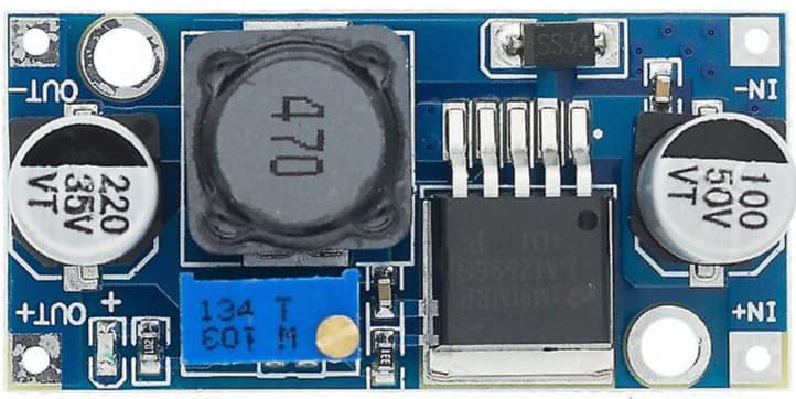
The LM2596 is a step-down (buck) DC-DC voltage regulator designed to efficiently convert a higher input voltage into a stable, lower output voltage. Manufactured by STEP DOWN DC TO DC, this regulator is capable of delivering up to 3A of output current. It features built-in thermal shutdown, current limiting, and high efficiency, making it a reliable choice for a wide range of applications.
Explore Projects Built with LM2596


Explore Projects Built with LM2596
Common Applications and Use Cases
- Power supply for microcontrollers and embedded systems
- Battery-powered devices
- Adjustable voltage regulators
- Industrial automation systems
- LED drivers
- Consumer electronics
Technical Specifications
The LM2596 is a versatile and robust component with the following key specifications:
| Parameter | Value |
|---|---|
| Input Voltage Range | 4.5V to 40V |
| Output Voltage Range | 1.23V to 37V (adjustable) |
| Maximum Output Current | 3A |
| Efficiency | Up to 90% |
| Switching Frequency | 150 kHz |
| Output Voltage Tolerance | ±4% |
| Operating Temperature Range | -40°C to +125°C |
| Protection Features | Thermal shutdown, current limiting |
Pin Configuration and Descriptions
The LM2596 is typically available in a 5-pin TO-220 package. Below is the pinout and description:
| Pin Number | Pin Name | Description |
|---|---|---|
| 1 | Input (Vin) | Connects to the input voltage source (4.5V to 40V). |
| 2 | Output (Vout) | Provides the regulated output voltage (1.23V to 37V). |
| 3 | Ground (GND) | Common ground for input and output. |
| 4 | Feedback (FB) | Used to set the output voltage via an external resistor divider. |
| 5 | ON/OFF | Enables or disables the regulator. Connect to GND to enable, or to Vin to disable. |
Usage Instructions
How to Use the LM2596 in a Circuit
- Input Voltage: Connect the input voltage source (4.5V to 40V) to the
Vinpin. Ensure the input voltage is at least 3V higher than the desired output voltage for proper regulation. - Output Voltage Adjustment: Use a resistor divider network connected to the
Feedback (FB)pin to set the desired output voltage. The output voltage can be calculated using the formula: [ V_{out} = V_{ref} \times \left(1 + \frac{R_2}{R_1}\right) ] where ( V_{ref} ) is 1.23V, and ( R_1 ) and ( R_2 ) are the resistors in the divider. - Output Capacitor: Place a low ESR capacitor (e.g., 100µF) at the output to stabilize the voltage and reduce ripple.
- Input Capacitor: Add a capacitor (e.g., 100µF) at the input to filter noise and improve stability.
- Inductor Selection: Choose an inductor with a suitable current rating (greater than 3A) and low DC resistance for optimal performance.
- Enable/Disable: To enable the regulator, connect the
ON/OFFpin to GND. To disable, connect it to Vin.
Example Circuit
Below is a typical application circuit for the LM2596:
Vin ----+----[C1]----+----+----> Vout
        |            |    |
       [L1]         [D1] [C2]
        |            |    |
       GND          GND  GND
- C1: Input capacitor (e.g., 100µF)
- L1: Inductor (e.g., 33µH)
- D1: Schottky diode (e.g., 1N5822)
- C2: Output capacitor (e.g., 100µF)
Arduino UNO Example
The LM2596 can be used to power an Arduino UNO by stepping down a higher voltage (e.g., 12V) to 5V. Below is an example code to read the output voltage using the Arduino's ADC:
// Define the analog pin connected to the LM2596 output
const int voltagePin = A0;

// Reference voltage for ADC (5V for Arduino UNO)
const float referenceVoltage = 5.0;

// ADC resolution (10-bit for Arduino UNO)
const int adcResolution = 1024;

void setup() {
  Serial.begin(9600); // Initialize serial communication
}

void loop() {
  int adcValue = analogRead(voltagePin); // Read the ADC value
  float outputVoltage = (adcValue * referenceVoltage) / adcResolution;

  // Print the output voltage to the Serial Monitor
  Serial.print("Output Voltage: ");
  Serial.print(outputVoltage);
  Serial.println(" V");

  delay(1000); // Wait for 1 second before the next reading
}
Important Considerations and Best Practices
- Use low ESR capacitors for better performance and reduced ripple.
- Ensure proper heat dissipation by using a heatsink if the regulator operates at high currents.
- Avoid exceeding the maximum input voltage (40V) or output current (3A) to prevent damage.
- Use a Schottky diode with a current rating higher than the output current to improve efficiency.
Troubleshooting and FAQs
Common Issues and Solutions
Output Voltage is Incorrect
- Verify the resistor divider values connected to the
Feedback (FB)pin. - Check for loose connections or damaged components.
- Verify the resistor divider values connected to the
Excessive Heat
- Ensure the input voltage is not too high relative to the output voltage.
- Use a heatsink or improve ventilation around the regulator.
No Output Voltage
- Confirm that the
ON/OFFpin is connected to GND to enable the regulator. - Check the input voltage and ensure it is within the specified range.
- Confirm that the
High Output Ripple
- Use low ESR capacitors at the input and output.
- Verify the inductor value and ensure it meets the design requirements.
FAQs
Q: Can the LM2596 be used for 5V to 3.3V conversion?
A: Yes, the LM2596 can step down 5V to 3.3V. Ensure the resistor divider is configured correctly for 3.3V output.
Q: What is the maximum efficiency of the LM2596?
A: The LM2596 can achieve up to 90% efficiency under optimal conditions.
Q: Can I use the LM2596 without a heatsink?
A: For low current applications (e.g., below 1A), a heatsink may not be necessary. However, for higher currents, a heatsink is recommended to prevent overheating.
Q: Is the LM2596 suitable for battery-powered devices?
A: Yes, the LM2596 is highly efficient and suitable for battery-powered applications, provided the input voltage is within the specified range.