
How to Use Adafruit Arcade Joystick: Examples, Pinouts, and Specs
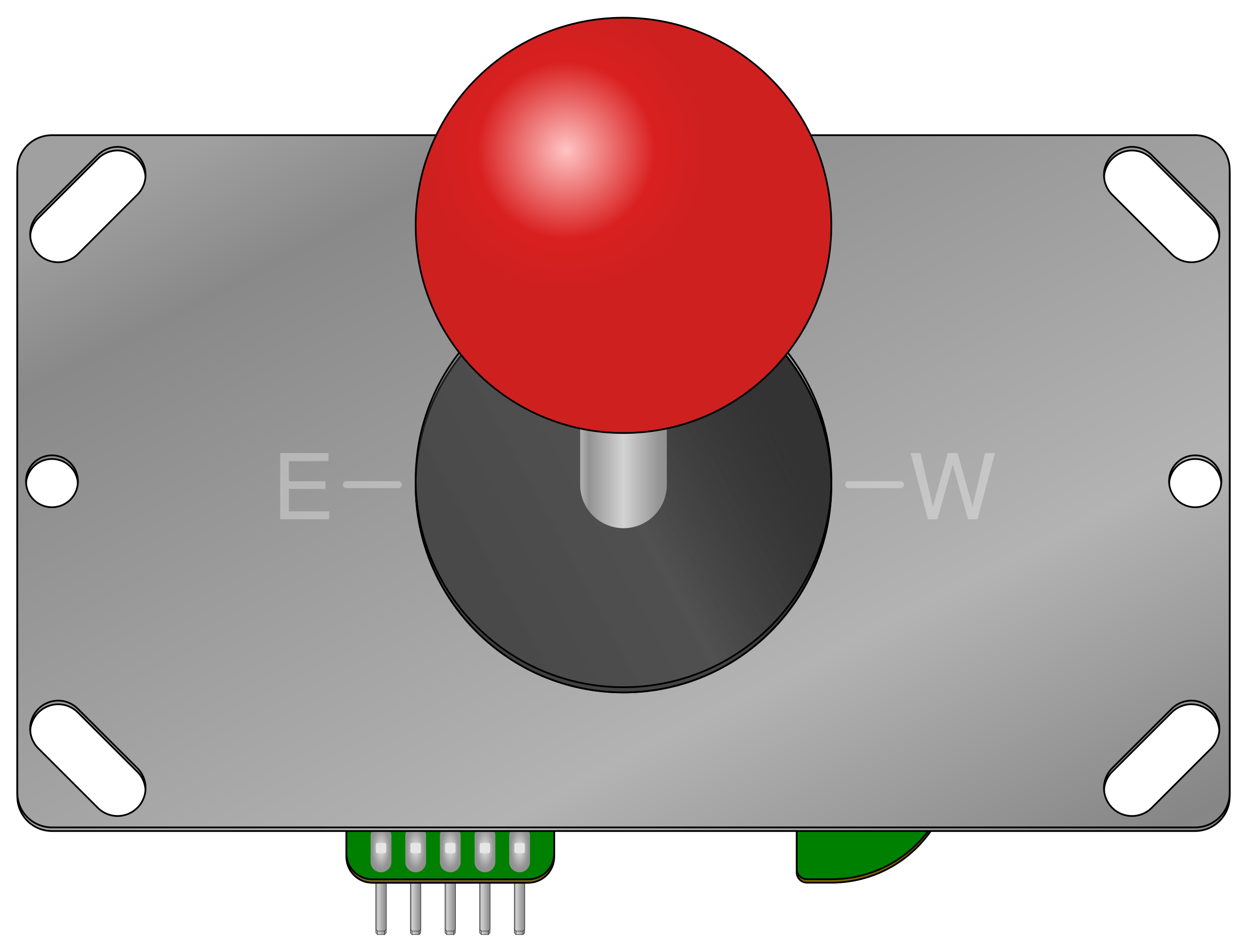
 Design with Adafruit Arcade Joystick in Cirkit Designer
Introduction
The Adafruit Arcade Joystick (Part ID: 480) is a high-quality joystick designed for arcade-style gaming and control applications. It features a robust construction, smooth movement, and precise control, making it ideal for gaming consoles, DIY arcade cabinets, robotics, and other interactive projects. The joystick is compatible with a variety of microcontrollers and can be easily integrated into custom setups.
Explore Projects Built with Adafruit Arcade Joystick
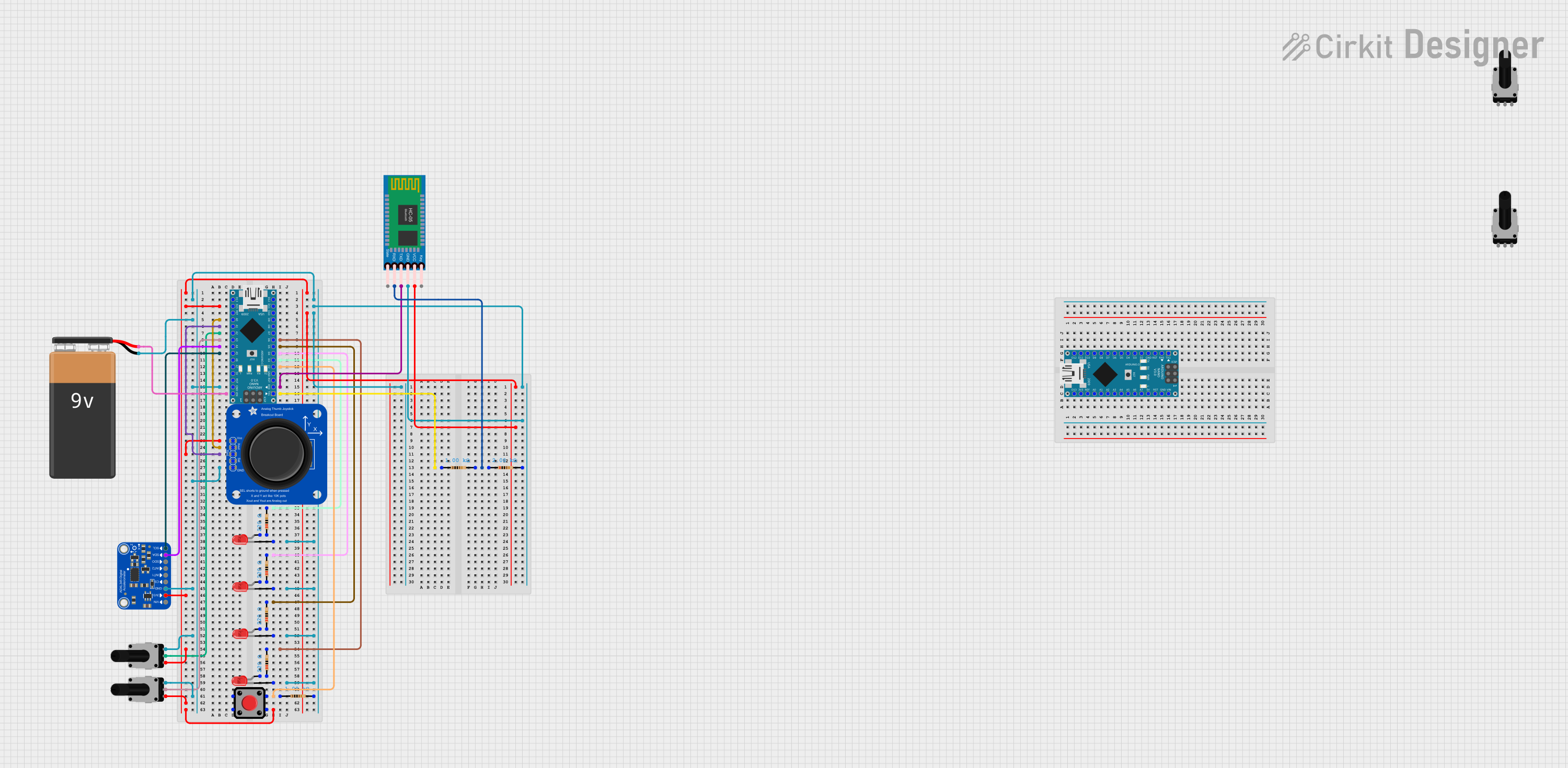 Open Project in Cirkit Designer
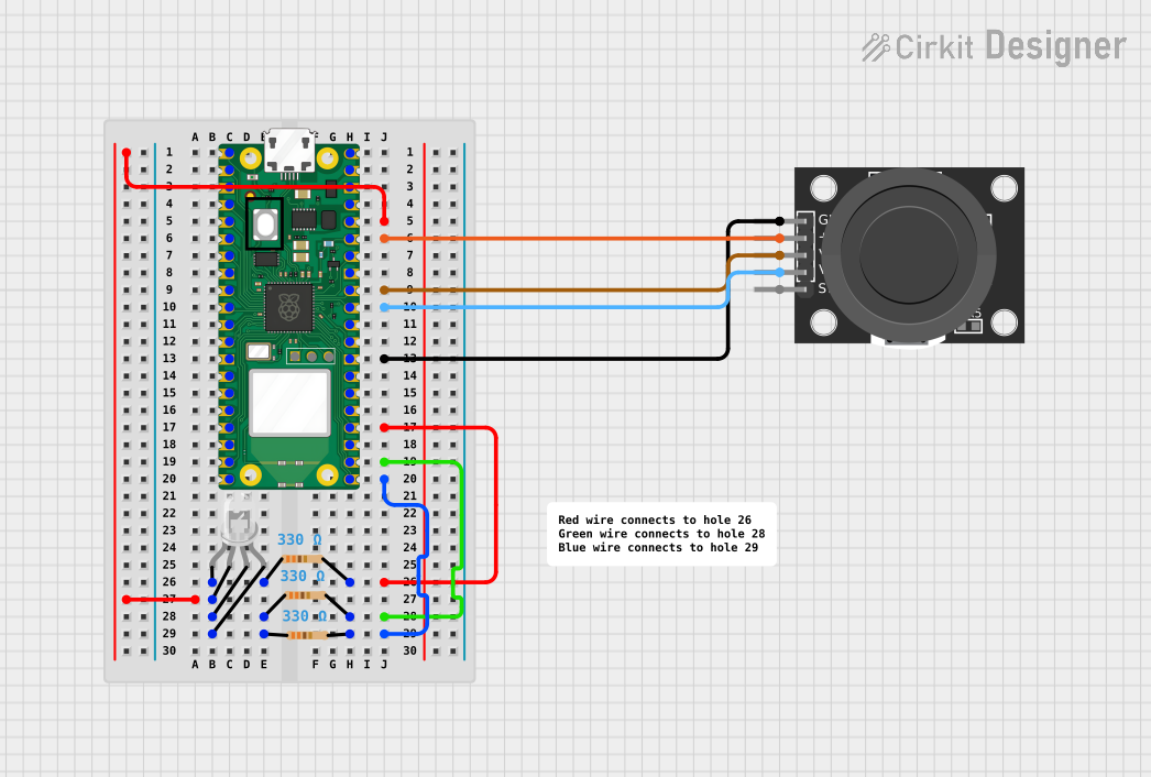 Open Project in Cirkit Designer
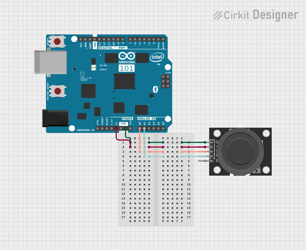 Open Project in Cirkit Designer
 Open Project in Cirkit Designer
Explore Projects Built with Adafruit Arcade Joystick
Open Project in Cirkit DesignerOpen Project in Cirkit DesignerOpen Project in Cirkit DesignerOpen Project in Cirkit DesignerCommon Applications
- DIY arcade gaming cabinets
- Retro gaming consoles
- Robotics control systems
- Interactive kiosks and displays
- Custom gaming controllers
Technical Specifications
The Adafruit Arcade Joystick is designed for durability and precision. Below are its key technical details:
| Specification | Details |
|---|---|
| Manufacturer | Adafruit |
| Part ID | 480 |
| Operating Voltage | 3.3V to 5V |
| Movement Directions | 4-way (Up, Down, Left, Right) |
| Switch Type | Microswitches (4 switches) |
| Mounting Hole Diameter | 5mm |
| Shaft Length | 35mm |
| Base Dimensions | 95mm x 60mm |
| Weight | 150g |
Pin Configuration and Descriptions
The joystick uses four microswitches, each corresponding to a direction. These switches are connected to individual pins for easy interfacing. Below is the pin configuration:
| Pin Name | Description |
|---|---|
| UP | Activates when the joystick is pushed upward |
| DOWN | Activates when the joystick is pushed downward |
| LEFT | Activates when the joystick is pushed left |
| RIGHT | Activates when the joystick is pushed right |
| GND | Common ground for all switches |
Usage Instructions
Connecting the Joystick
- Wiring: Connect each directional pin (UP, DOWN, LEFT, RIGHT) to a digital input pin on your microcontroller. Connect the GND pin to the ground of your microcontroller.
- Power Supply: The joystick operates at 3.3V to 5V, so ensure your microcontroller's logic level matches this range.
- Debouncing: Since the joystick uses mechanical switches, consider implementing software debouncing to avoid false triggers.
Example: Using with Arduino UNO
Below is an example of how to connect and read the joystick's state using an Arduino UNO:
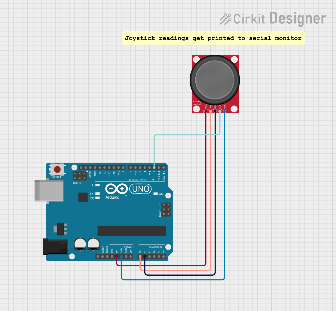
Circuit Diagram
- Connect the joystick's UP, DOWN, LEFT, and RIGHT pins to Arduino digital pins 2, 3, 4, and 5, respectively.
- Connect the GND pin of the joystick to the Arduino's GND.
Arduino Code
// Define joystick pins
const int pinUp = 2;    // Pin for UP direction
const int pinDown = 3;  // Pin for DOWN direction
const int pinLeft = 4;  // Pin for LEFT direction
const int pinRight = 5; // Pin for RIGHT direction

void setup() {
  // Set joystick pins as inputs with pull-up resistors
  pinMode(pinUp, INPUT_PULLUP);
  pinMode(pinDown, INPUT_PULLUP);
  pinMode(pinLeft, INPUT_PULLUP);
  pinMode(pinRight, INPUT_PULLUP);

  // Initialize serial communication for debugging
  Serial.begin(9600);
}

void loop() {
  // Read joystick state
  bool upState = digitalRead(pinUp) == LOW;    // LOW means pressed
  bool downState = digitalRead(pinDown) == LOW;
  bool leftState = digitalRead(pinLeft) == LOW;
  bool rightState = digitalRead(pinRight) == LOW;

  // Print joystick state to the Serial Monitor
  if (upState) {
    Serial.println("Joystick moved UP");
  }
  if (downState) {
    Serial.println("Joystick moved DOWN");
  }
  if (leftState) {
    Serial.println("Joystick moved LEFT");
  }
  if (rightState) {
    Serial.println("Joystick moved RIGHT");
  }

  delay(100); // Small delay to avoid spamming the Serial Monitor
}
Best Practices
- Use proper pull-up or pull-down resistors if your microcontroller does not support internal pull-ups.
- Mount the joystick securely to avoid movement during operation.
- Test the joystick's responsiveness and adjust debounce timing in software if necessary.
Troubleshooting and FAQs
Common Issues
Joystick Not Responding
- Cause: Loose or incorrect wiring.
- Solution: Double-check all connections and ensure the joystick is properly grounded.
False Triggers or Erratic Behavior
- Cause: Switch bouncing or electrical noise.
- Solution: Implement software debouncing or use external capacitors for hardware debouncing.
Directional Inputs Not Detected
- Cause: Faulty microswitch or broken connection.
- Solution: Test each microswitch with a multimeter and replace if necessary.
FAQs
Can this joystick be used with Raspberry Pi?
- Yes, the joystick can be connected to the GPIO pins of a Raspberry Pi. Use pull-up resistors and configure the GPIO pins as inputs.
Is the joystick compatible with 12V systems?
- No, the joystick is designed for 3.3V to 5V systems. Using higher voltages may damage the switches.
How durable is the joystick?
- The joystick is built for arcade-style use and can withstand heavy usage. However, avoid excessive force to prolong its lifespan.
Can I use this joystick for analog input?
- No, this joystick is a digital component with discrete directional switches. For analog input, consider using a potentiometer-based joystick.
By following this documentation, you can effectively integrate the Adafruit Arcade Joystick into your projects and troubleshoot any issues that arise.