How to Use ZY12PDN: Examples, Pinouts, and Specs
Introduction
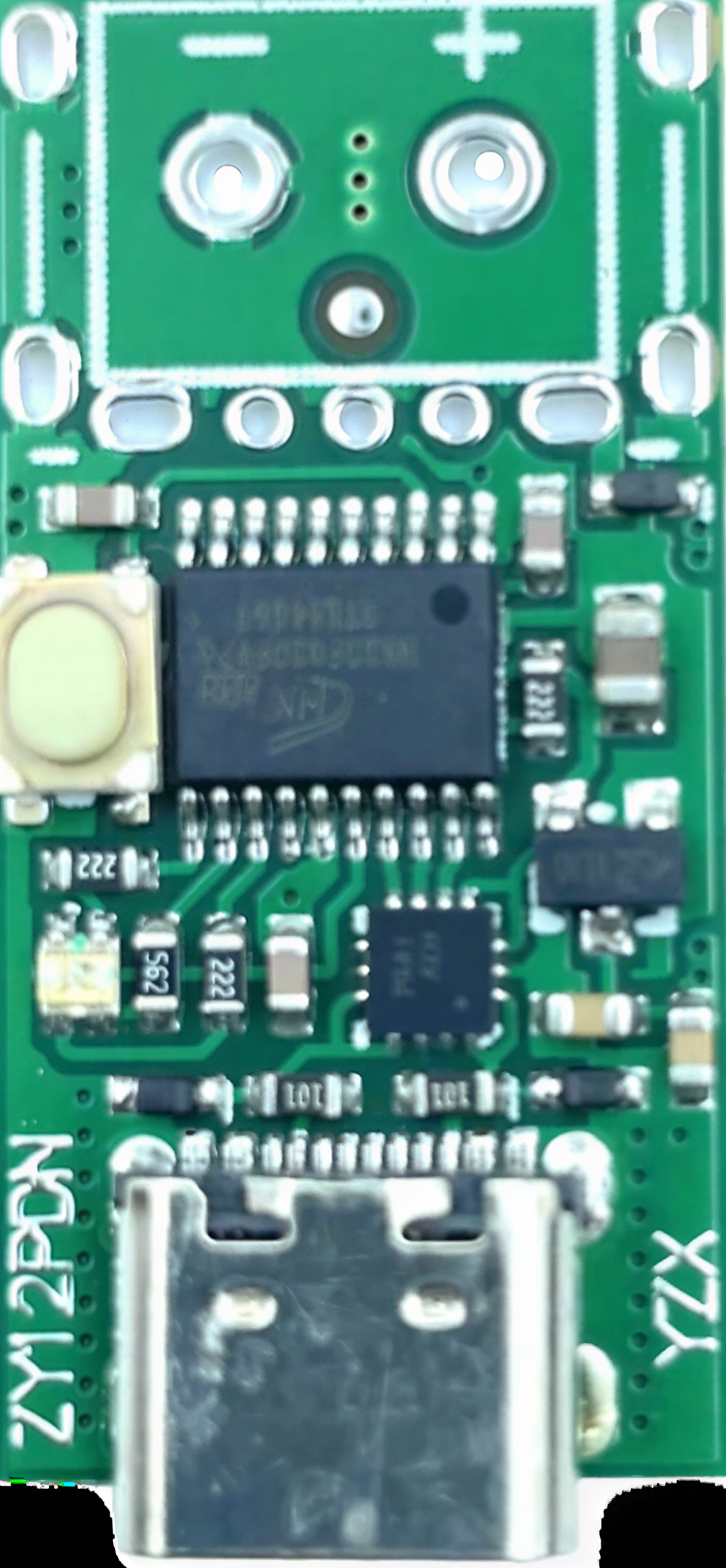
The ZY12PDN is a high-performance voltage regulator designed to provide a stable output voltage with low dropout. It is widely used in applications requiring precise voltage regulation, such as power management systems, battery-powered devices, and embedded systems. Its compact design and reliable performance make it a popular choice for both hobbyists and professionals.
Explore Projects Built with ZY12PDN
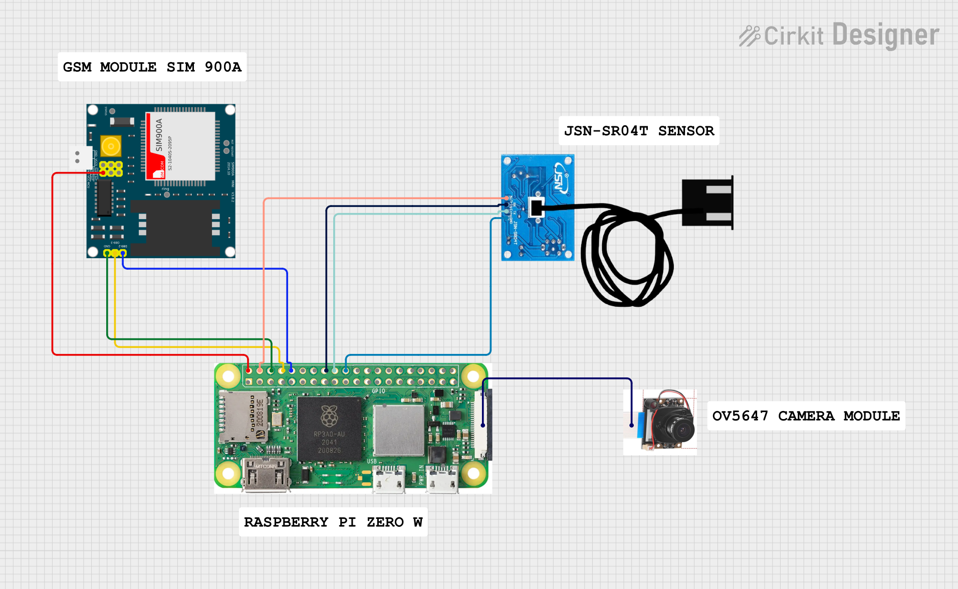


Explore Projects Built with ZY12PDN
Common Applications
- Power supply regulation for microcontrollers and sensors
- Battery-powered devices
- Portable electronics
- Embedded systems
- USB Power Delivery (PD) applications
Technical Specifications
Key Technical Details
| Parameter | Value |
|---|---|
| Input Voltage Range | 5V to 20V |
| Output Voltage Options | 5V, 9V, 12V, 15V, 20V |
| Maximum Output Current | 3A |
| Dropout Voltage | < 0.5V |
| Efficiency | Up to 95% |
| Operating Temperature | -40°C to +85°C |
| Package Type | SMD (Surface-Mount Device) |
Pin Configuration and Descriptions
| Pin Number | Pin Name | Description |
|---|---|---|
| 1 | VIN | Input voltage pin (5V to 20V) |
| 2 | GND | Ground pin |
| 3 | VOUT | Regulated output voltage pin |
| 4 | CC1 | USB Type-C Configuration Channel 1 |
| 5 | CC2 | USB Type-C Configuration Channel 2 |
Usage Instructions
How to Use the ZY12PDN in a Circuit
- Power Input: Connect the VIN pin to a power source within the range of 5V to 20V. Ensure the input voltage is stable and within the specified range.
- Ground Connection: Connect the GND pin to the ground of your circuit.
- Output Voltage: The VOUT pin provides the regulated output voltage. Connect this pin to the load or circuit requiring the regulated voltage.
- USB PD Configuration: If using the ZY12PDN in a USB Power Delivery application, connect the CC1 and CC2 pins to the appropriate configuration channels of the USB Type-C connector.
Important Considerations and Best Practices
- Use appropriate decoupling capacitors (e.g., 10µF and 0.1µF) near the VIN and VOUT pins to ensure stable operation and reduce noise.
- Ensure the input voltage is within the specified range to prevent damage to the component.
- If using the ZY12PDN in a USB PD application, ensure proper configuration of the CC1 and CC2 pins to negotiate the desired voltage level.
- Avoid exceeding the maximum output current of 3A to prevent overheating or damage.
Example: Using ZY12PDN with Arduino UNO
The ZY12PDN can be used to power an Arduino UNO by providing a stable 5V output. Below is an example circuit and code to demonstrate its usage:
Circuit Setup
- Connect the VIN pin of the ZY12PDN to a 12V DC power source.
- Connect the GND pin of the ZY12PDN to the ground of the power source and Arduino UNO.
- Connect the VOUT pin of the ZY12PDN to the 5V pin of the Arduino UNO.
Arduino Code Example
// Example code to blink an LED connected to Arduino UNO
// Ensure the Arduino is powered via the ZY12PDN regulator

const int ledPin = 13; // Pin connected to the onboard LED

void setup() {
  pinMode(ledPin, OUTPUT); // Set the LED pin as an output
}

void loop() {
  digitalWrite(ledPin, HIGH); // Turn the LED on
  delay(1000);                // Wait for 1 second
  digitalWrite(ledPin, LOW);  // Turn the LED off
  delay(1000);                // Wait for 1 second
}
Troubleshooting and FAQs
Common Issues and Solutions
No Output Voltage:
- Ensure the input voltage is within the specified range (5V to 20V).
- Check all connections, especially VIN, GND, and VOUT.
- Verify that the load does not exceed the maximum output current of 3A.
Overheating:
- Ensure proper heat dissipation by using a heatsink or placing the component in a well-ventilated area.
- Check if the load current exceeds the maximum rating.
Unstable Output Voltage:
- Add decoupling capacitors (e.g., 10µF and 0.1µF) near the VIN and VOUT pins.
- Verify that the input voltage is stable and free from significant noise.
FAQs
Q: Can the ZY12PDN be used with a USB Type-C connector?
A: Yes, the ZY12PDN is designed for USB Power Delivery applications and can be used with a USB Type-C connector. Ensure proper configuration of the CC1 and CC2 pins.
Q: What is the maximum output current of the ZY12PDN?
A: The ZY12PDN can provide a maximum output current of 3A.
Q: What should I do if the ZY12PDN overheats?
A: Check the load current and ensure it does not exceed 3A. Use a heatsink or improve ventilation to enhance heat dissipation.
Q: Can I use the ZY12PDN to power a microcontroller?
A: Yes, the ZY12PDN is suitable for powering microcontrollers, including Arduino boards, as long as the input and output voltage requirements are met.