How to Use DC-DC Boost Module: Examples, Pinouts, and Specs
Introduction
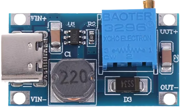
The DC-DC Boost Module (MT3608), manufactured by AliExpress, is a compact and efficient power converter designed to step up (boost) an input voltage to a higher output voltage. This module is based on the MT3608 chip and is widely used in applications where a stable, higher voltage is required from a lower voltage source, such as batteries. It is ideal for powering devices that require a higher voltage than the available input source.
Explore Projects Built with DC-DC Boost Module


Explore Projects Built with DC-DC Boost Module
Common Applications and Use Cases
- Powering microcontrollers and sensors from a single-cell Li-ion battery.
- Driving LED strips or displays requiring higher voltage.
- Extending the voltage range of portable devices.
- DIY electronics projects and prototyping.
- Solar-powered systems.
Technical Specifications
Below are the key technical details of the MT3608 DC-DC Boost Module:
| Parameter | Value |
|---|---|
| Input Voltage Range | 2V to 24V |
| Output Voltage Range | 5V to 28V (adjustable via potentiometer) |
| Maximum Output Current | 2A (depends on input voltage and load) |
| Efficiency | Up to 93% (depending on load and input) |
| Switching Frequency | 1.2 MHz |
| Dimensions | 36mm x 17mm x 6mm |
Pin Configuration and Descriptions
The MT3608 DC-DC Boost Module has the following pinout:
| Pin Name | Description |
|---|---|
| VIN | Positive input voltage terminal (connect to the power source). |
| GND | Ground terminal (common ground for input and output). |
| VOUT | Positive output voltage terminal (connect to the load). |
| Potentiometer | Adjustable screw to set the output voltage (clockwise to increase voltage). |
Usage Instructions
How to Use the Component in a Circuit
Connect the Input Voltage:
- Connect the positive terminal of your power source to the
VINpin. - Connect the negative terminal of your power source to the
GNDpin.
- Connect the positive terminal of your power source to the
Connect the Output Voltage:
- Connect the
VOUTpin to the positive terminal of your load. - Connect the
GNDpin to the negative terminal of your load.
- Connect the
Adjust the Output Voltage:
- Use a small screwdriver to turn the onboard potentiometer.
- Turn clockwise to increase the output voltage or counterclockwise to decrease it.
- Use a multimeter to measure the output voltage while adjusting.
Power On:
- Ensure all connections are secure and within the module's specifications.
- Power on the input source and verify the output voltage.
Important Considerations and Best Practices
- Input Voltage Limit: Ensure the input voltage does not exceed 24V to avoid damaging the module.
- Output Voltage Limit: Do not exceed 28V on the output to prevent overloading the module.
- Current Limit: The module can provide up to 2A, but this depends on the input voltage and load. Exceeding this may cause overheating or failure.
- Heat Dissipation: For high current loads, consider adding a heatsink to the module for better thermal management.
- Polarity: Double-check the polarity of your connections to avoid damage.
Example: Using the MT3608 with an Arduino UNO
The MT3608 can be used to power an Arduino UNO from a 3.7V Li-ion battery. Below is an example circuit and code:
Circuit Connections
- Connect the battery's positive terminal to
VINand negative terminal toGND. - Adjust the potentiometer to output 5V (required for the Arduino UNO).
- Connect the
VOUTpin to the Arduino's5Vpin andGNDto the Arduino'sGND.
Example Code
// Example code to blink an LED using Arduino UNO powered by MT3608
// Ensure the MT3608 is set to output 5V before connecting to the Arduino.

const int ledPin = 13; // Pin connected to the onboard LED

void setup() {
  pinMode(ledPin, OUTPUT); // Set the LED pin as an output
}

void loop() {
  digitalWrite(ledPin, HIGH); // Turn the LED on
  delay(1000);                // Wait for 1 second
  digitalWrite(ledPin, LOW);  // Turn the LED off
  delay(1000);                // Wait for 1 second
}
Troubleshooting and FAQs
Common Issues and Solutions
No Output Voltage:
- Check the input voltage and ensure it is within the 2V to 24V range.
- Verify all connections and ensure the polarity is correct.
- Adjust the potentiometer to ensure the output voltage is not set too low.
Overheating:
- Ensure the load current does not exceed 2A.
- Add a heatsink or improve ventilation if the module is used at high currents.
Output Voltage Fluctuations:
- Check for loose connections or poor solder joints.
- Ensure the input voltage is stable and within the specified range.
Cannot Achieve Desired Output Voltage:
- Verify that the input voltage is sufficient to achieve the desired output.
- Ensure the potentiometer is adjusted correctly.
FAQs
Q: Can I use the MT3608 to power a Raspberry Pi?
A: Yes, but ensure the output voltage is set to 5V and the current demand does not exceed 2A.
Q: Is the module protected against reverse polarity?
A: No, the MT3608 does not have reverse polarity protection. Always double-check your connections.
Q: Can I use this module with a solar panel?
A: Yes, as long as the solar panel's output voltage and current are within the module's input range.
Q: How do I know if the module is damaged?
A: If there is no output voltage despite correct connections and input voltage, the module may be damaged. Check for visible signs of damage, such as burnt components.
By following this documentation, you can effectively use the MT3608 DC-DC Boost Module in your projects.