How to Use DC-DC 5v 3A: Examples, Pinouts, and Specs
Introduction
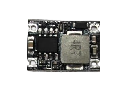
The DC-DC 5V 3A converter is a versatile electronic component designed to step down or step up voltage levels to provide a stable 5V output. It is capable of delivering a maximum output current of 3A, making it suitable for powering a wide range of devices, including microcontrollers, sensors, and portable electronics. This component is commonly used in battery-powered systems, USB power supplies, and embedded applications where a reliable 5V power source is required.
Explore Projects Built with DC-DC 5v 3A


Explore Projects Built with DC-DC 5v 3A
Common Applications and Use Cases
- Powering microcontrollers such as Arduino, Raspberry Pi, and ESP32.
- Providing a stable 5V supply for sensors, modules, and peripherals.
- Battery-powered devices requiring voltage regulation.
- USB power banks and portable chargers.
- Robotics and IoT applications.
Technical Specifications
The following table outlines the key technical specifications of the DC-DC 5V 3A converter:
| Parameter | Value |
|---|---|
| Input Voltage Range | 6V to 24V (step-down mode) |
| Output Voltage | 5V (regulated) |
| Maximum Output Current | 3A |
| Efficiency | Up to 95% |
| Switching Frequency | 150 kHz |
| Operating Temperature | -40°C to +85°C |
| Dimensions | Varies by module (e.g., 22x17mm) |
Pin Configuration and Descriptions
The DC-DC 5V 3A converter typically has the following pin configuration:
| Pin Name | Description |
|---|---|
| VIN | Input voltage pin (connect to power source) |
| GND | Ground pin (common ground for input and output) |
| VOUT | Regulated 5V output pin (connect to load) |
| EN (optional) | Enable pin (used to turn the module on/off, active high) |
Note: Some modules may include additional pins or features such as a potentiometer for voltage adjustment. Refer to the specific module's datasheet for details.
Usage Instructions
How to Use the Component in a Circuit
Connect the Input Voltage:
- Connect the VIN pin to a DC power source within the specified input voltage range (e.g., 6V to 24V).
- Ensure the power source can supply sufficient current for your load.
Connect the Ground:
- Connect the GND pin to the ground of your circuit.
Connect the Output Voltage:
- Connect the VOUT pin to the device or circuit requiring a 5V power supply.
- Ensure the total current draw does not exceed 3A.
Optional Enable Pin:
- If the module includes an EN pin, connect it to a logic HIGH signal (e.g., 3.3V or 5V) to enable the converter. Leave it unconnected or pull it LOW to disable the module.
Important Considerations and Best Practices
- Heat Dissipation: At high currents, the module may generate heat. Use a heatsink or ensure proper ventilation to prevent overheating.
- Input Voltage Range: Ensure the input voltage is within the specified range to avoid damaging the module.
- Load Current: Do not exceed the maximum output current of 3A to prevent overloading the module.
- Capacitors: Use appropriate input and output capacitors (e.g., 10µF to 100µF) to improve stability and reduce noise.
- Polarity: Double-check the polarity of the input and output connections to avoid damage.
Example: Using with Arduino UNO
The DC-DC 5V 3A converter can be used to power an Arduino UNO. Below is an example circuit and code:
Circuit Connections
- Connect the VIN pin of the DC-DC converter to a 9V battery or DC adapter.
- Connect the GND pin of the converter to the Arduino GND pin.
- Connect the VOUT pin of the converter to the Arduino 5V pin.
Arduino Code Example
// Example code to blink an LED using Arduino UNO powered by DC-DC 5V 3A converter

const int ledPin = 13; // Pin connected to the onboard LED

void setup() {
  pinMode(ledPin, OUTPUT); // Set the LED pin as an output
}

void loop() {
  digitalWrite(ledPin, HIGH); // Turn the LED on
  delay(1000);                // Wait for 1 second
  digitalWrite(ledPin, LOW);  // Turn the LED off
  delay(1000);                // Wait for 1 second
}
Note: Ensure the total current draw of the Arduino and connected peripherals does not exceed 3A.
Troubleshooting and FAQs
Common Issues and Solutions
No Output Voltage:
- Check the input voltage and ensure it is within the specified range.
- Verify the connections to VIN, GND, and VOUT.
- If the module has an EN pin, ensure it is connected to a logic HIGH signal.
Overheating:
- Ensure the load current does not exceed 3A.
- Improve ventilation or add a heatsink to the module.
Output Voltage Fluctuations:
- Add input and output capacitors to stabilize the voltage.
- Check for loose or poor connections.
Module Not Powering On:
- Verify the polarity of the input connections.
- Check for any visible damage to the module.
FAQs
Q: Can I use this module to power a Raspberry Pi?
A: Yes, the DC-DC 5V 3A converter can power a Raspberry Pi. Ensure the input power source can supply sufficient current, and the total load does not exceed 3A.
Q: Can I adjust the output voltage?
A: Most DC-DC 5V 3A converters have a fixed 5V output. If your module includes a potentiometer, you may be able to adjust the output voltage. Refer to the module's datasheet for details.
Q: Is reverse polarity protection included?
A: Many modules do not include reverse polarity protection. Always double-check the polarity of your connections to avoid damage.
Q: Can I use this module with a solar panel?
A: Yes, as long as the solar panel's output voltage is within the input voltage range of the module. Use capacitors to stabilize the input voltage if necessary.