How to Use step down buck converter lm2596: Examples, Pinouts, and Specs
Introduction
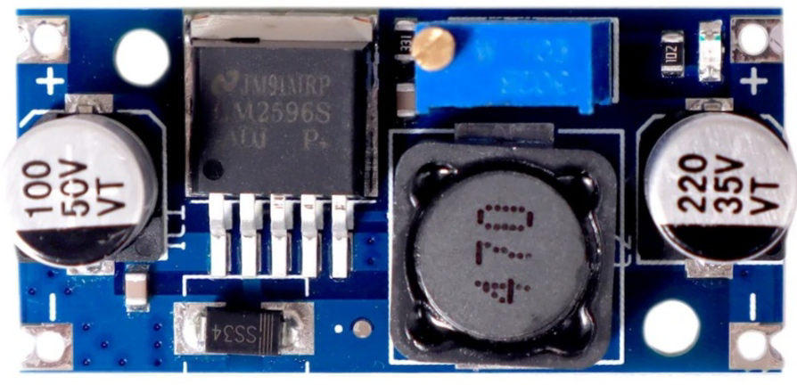
The LM2596, manufactured by STMicroelectronics (Part ID: UNO), is a step-down (buck) voltage regulator designed for efficient voltage conversion. It is capable of converting a higher input voltage to a stable, lower output voltage with high efficiency. The LM2596 can deliver up to 3A of output current, making it suitable for a wide range of power supply applications. It also includes built-in thermal shutdown and current limiting features to ensure safe operation.
Explore Projects Built with step down buck converter lm2596


Explore Projects Built with step down buck converter lm2596
Common Applications and Use Cases
- DC-DC power supply modules
- Battery-powered devices
- Voltage regulation for microcontrollers and sensors
- LED drivers
- Industrial and automotive electronics
Technical Specifications
Key Technical Details
| Parameter | Value |
|---|---|
| Input Voltage Range | 4.5V to 40V |
| Output Voltage Range | 1.23V to 37V (adjustable) |
| Output Current | Up to 3A |
| Efficiency | Up to 90% |
| Switching Frequency | 150 kHz |
| Thermal Shutdown | Yes |
| Current Limiting | Yes |
| Operating Temperature | -40°C to +125°C |
| Package Type | TO-220, TO-263, or similar |
Pin Configuration and Descriptions
The LM2596 typically comes in a 5-pin package. Below is the pinout description:
| Pin Number | Pin Name | Description |
|---|---|---|
| 1 | VIN | Input voltage pin. Connect to the unregulated DC input voltage. |
| 2 | Output | Regulated output voltage pin. Connect to the load. |
| 3 | Ground | Ground pin. Connect to the circuit ground. |
| 4 | Feedback | Feedback pin. Used to set the output voltage via an external resistor divider. |
| 5 | ON/OFF | Enable pin. Connect to ground to enable the regulator, or to VIN to disable. |
Usage Instructions
How to Use the LM2596 in a Circuit
- Input Voltage: Connect the input voltage (4.5V to 40V) to the VIN pin. Ensure the input voltage is higher than the desired output voltage by at least 3V for proper regulation.
- Output Voltage Adjustment: Use a resistor divider network connected to the Feedback pin to set the desired output voltage. The output voltage can be calculated using the formula: [ V_{OUT} = V_{REF} \times \left(1 + \frac{R1}{R2}\right) ] where ( V_{REF} ) is 1.23V, and ( R1 ) and ( R2 ) are the resistors in the divider.
- Output Capacitor: Place a low ESR capacitor (e.g., 100µF) at the output pin to stabilize the voltage and reduce ripple.
- Input Capacitor: Add a capacitor (e.g., 100µF) at the input pin to filter noise and improve stability.
- Inductor Selection: Choose an inductor with a current rating higher than the maximum load current and an appropriate inductance value (e.g., 33µH to 100µH) for your application.
- Enable Pin: Connect the ON/OFF pin to ground to enable the regulator. If unused, it can be left floating.
Important Considerations and Best Practices
- Ensure proper heat dissipation by using a heatsink or adequate PCB thermal design, especially when operating at high currents.
- Use short and thick traces for the input and output connections to minimize resistance and voltage drops.
- Place the input and output capacitors as close as possible to the LM2596 pins to reduce noise and improve stability.
- Avoid exceeding the maximum input voltage (40V) or output current (3A) to prevent damage to the component.
Example: Connecting LM2596 to an Arduino UNO
The LM2596 can be used to power an Arduino UNO by stepping down a higher voltage (e.g., 12V) to 5V. Below is an example circuit and Arduino code:
Circuit Connections
- Connect the input voltage (e.g., 12V) to the VIN pin of the LM2596.
- Set the output voltage to 5V using the resistor divider or an adjustable module.
- Connect the output pin of the LM2596 to the 5V pin of the Arduino UNO.
- Connect the ground pin of the LM2596 to the GND pin of the Arduino UNO.
Arduino Code Example
// Example code to blink an LED using Arduino UNO powered by LM2596
// Ensure the LM2596 output is set to 5V before connecting to the Arduino

const int ledPin = 13; // Built-in LED pin on Arduino UNO

void setup() {
  pinMode(ledPin, OUTPUT); // Set LED pin as output
}

void loop() {
  digitalWrite(ledPin, HIGH); // Turn the LED on
  delay(1000);                // Wait for 1 second
  digitalWrite(ledPin, LOW);  // Turn the LED off
  delay(1000);                // Wait for 1 second
}
Troubleshooting and FAQs
Common Issues and Solutions
No Output Voltage:
- Check if the input voltage is within the specified range (4.5V to 40V).
- Ensure the ON/OFF pin is connected to ground to enable the regulator.
- Verify the resistor divider network is correctly configured for the desired output voltage.
Excessive Heat:
- Ensure the load current does not exceed 3A.
- Use a heatsink or improve PCB thermal design to dissipate heat effectively.
Output Voltage Instability:
- Check the input and output capacitors for proper values and low ESR.
- Ensure the inductor is correctly rated and not saturating under load.
High Output Ripple:
- Use capacitors with lower ESR and increase their capacitance if necessary.
- Place the capacitors as close as possible to the LM2596 pins.
FAQs
Q: Can the LM2596 be used with a battery as the input source?
A: Yes, the LM2596 can be used with a battery as long as the input voltage is within the specified range (4.5V to 40V).
Q: How do I calculate the resistor values for the feedback network?
A: Use the formula ( V_{OUT} = V_{REF} \times \left(1 + \frac{R1}{R2}\right) ), where ( V_{REF} = 1.23V ). Choose ( R2 ) (e.g., 1kΩ) and calculate ( R1 ) based on the desired output voltage.
Q: Can the LM2596 power multiple devices simultaneously?
A: Yes, as long as the total current draw does not exceed 3A and the output voltage remains stable.
Q: Is the LM2596 suitable for audio applications?
A: The LM2596 may introduce switching noise, which could affect sensitive audio circuits. Consider using additional filtering or a linear regulator for such applications.