How to Use 5V Regulator: Examples, Pinouts, and Specs
Introduction
The AS7805AT-E1 by Diodes Inc. is a 5V linear voltage regulator designed to provide a stable and reliable 5V output from a higher input voltage. This component is widely used in electronic circuits to ensure a consistent power supply, protecting sensitive components from voltage fluctuations. Its robust design and ease of use make it a popular choice for both hobbyists and professionals.
Explore Projects Built with 5V Regulator


Explore Projects Built with 5V Regulator
Common Applications and Use Cases
- Power supply for microcontrollers (e.g., Arduino, Raspberry Pi)
- Voltage regulation in battery-powered devices
- Stabilizing power for sensors, motors, and other peripherals
- General-purpose DC voltage regulation in electronic circuits
Technical Specifications
The following table outlines the key technical details of the AS7805AT-E1:
| Parameter | Value |
|---|---|
| Output Voltage | 5V ± 2% |
| Input Voltage Range | 7V to 25V |
| Maximum Output Current | 1.5A |
| Dropout Voltage | 2V (typical) |
| Quiescent Current | 5mA (typical) |
| Operating Temperature | -40°C to +125°C |
| Package Type | TO-220 |
Pin Configuration and Descriptions
The AS7805AT-E1 is a 3-pin device with the following pinout:
| Pin Number | Pin Name | Description |
|---|---|---|
| 1 | Input (IN) | Connect to the unregulated input voltage (7V–25V). |
| 2 | Ground (GND) | Common ground for input and output. |
| 3 | Output (OUT) | Provides the regulated 5V output. |
Usage Instructions
How to Use the Component in a Circuit
- Input Voltage: Connect a DC voltage source (7V–25V) to the Input (IN) pin. Ensure the input voltage is at least 2V higher than the desired 5V output to account for the dropout voltage.
- Output Voltage: Connect the Output (OUT) pin to the load or circuit requiring a 5V supply.
- Ground Connection: Connect the Ground (GND) pin to the common ground of the circuit.
- Capacitors: Add decoupling capacitors to improve stability and reduce noise:
- A 0.33µF capacitor between the Input (IN) pin and ground.
- A 0.1µF capacitor between the Output (OUT) pin and ground.
Important Considerations and Best Practices
- Heat Dissipation: The regulator may generate heat during operation, especially at higher input voltages or currents. Use a heatsink with the TO-220 package to prevent overheating.
- Input Voltage: Avoid exceeding the maximum input voltage of 25V to prevent damage to the regulator.
- Load Current: Ensure the load does not exceed the maximum output current of 1.5A.
- Bypass Capacitors: Always use the recommended capacitors to ensure stable operation and minimize voltage ripple.
Example: Connecting to an Arduino UNO
The AS7805AT-E1 can be used to power an Arduino UNO by providing a stable 5V supply. Below is an example circuit and Arduino code:
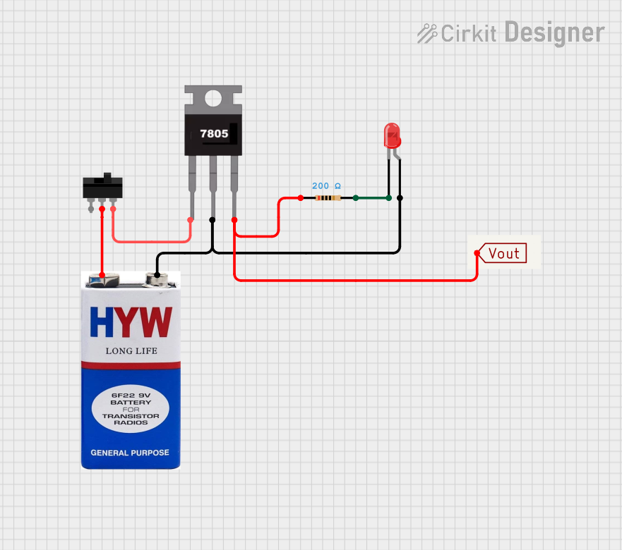
Circuit Setup
- Connect a 9V battery to the Input (IN) pin of the regulator.
- Connect the Output (OUT) pin to the 5V pin of the Arduino UNO.
- Connect the Ground (GND) pin to the GND pin of the Arduino UNO.
Arduino Code
// Example code to blink an LED using the 5V regulator as a power source
// Ensure the 5V regulator is properly connected to the Arduino UNO

const int ledPin = 13; // Built-in LED pin on Arduino UNO

void setup() {
  pinMode(ledPin, OUTPUT); // Set the LED pin as an output
}

void loop() {
  digitalWrite(ledPin, HIGH); // Turn the LED on
  delay(1000);                // Wait for 1 second
  digitalWrite(ledPin, LOW);  // Turn the LED off
  delay(1000);                // Wait for 1 second
}
Troubleshooting and FAQs
Common Issues and Solutions
No Output Voltage
- Cause: Insufficient input voltage.
- Solution: Ensure the input voltage is at least 7V.
Overheating
- Cause: Excessive current draw or high input voltage.
- Solution: Use a heatsink and ensure the load current does not exceed 1.5A.
Voltage Instability
- Cause: Missing or incorrect decoupling capacitors.
- Solution: Add a 0.33µF capacitor on the input and a 0.1µF capacitor on the output.
Output Voltage Too Low
- Cause: High dropout voltage due to low input voltage.
- Solution: Increase the input voltage to at least 2V above the output voltage.
FAQs
Q: Can I use the AS7805AT-E1 with a 12V input?
A: Yes, the regulator can handle input voltages up to 25V. A 12V input is well within the acceptable range.
Q: Do I need a heatsink for low-current applications?
A: For currents below 500mA, a heatsink is typically not required. However, for higher currents or prolonged use, a heatsink is recommended.
Q: Can I use this regulator to power a 3.3V device?
A: No, the AS7805AT-E1 provides a fixed 5V output. Use a 3.3V regulator for 3.3V devices.
Q: What happens if I reverse the input and output connections?
A: Reversing the connections can damage the regulator. Always double-check the pinout before powering the circuit.