How to Use IRF540NPBF: Examples, Pinouts, and Specs
Introduction
The IRF540NPBF is an N-channel MOSFET manufactured by Infineon Technologies. It is designed for high-speed switching applications and features a low on-resistance, enabling efficient power delivery. This component is widely used in power management, motor control circuits, DC-DC converters, and other high-current applications. Its robust design and high current-handling capability make it a popular choice for both industrial and hobbyist projects.
Explore Projects Built with IRF540NPBF


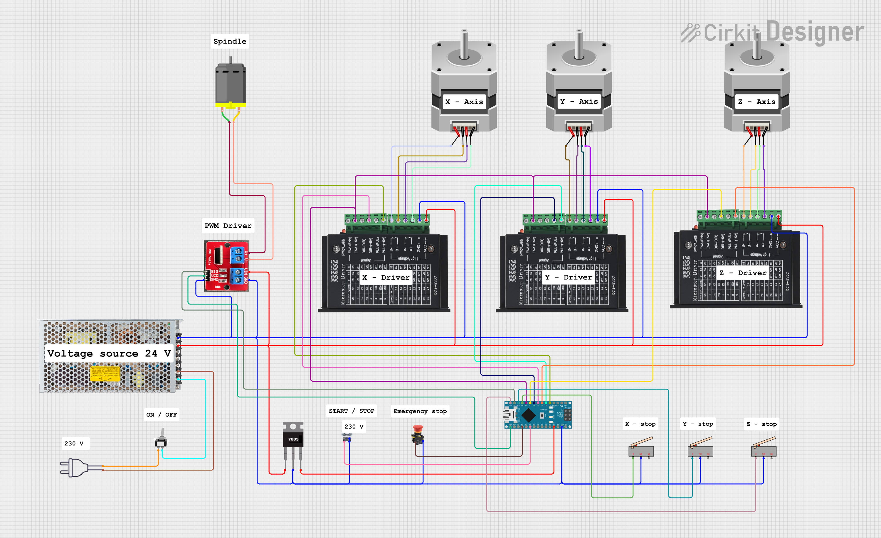
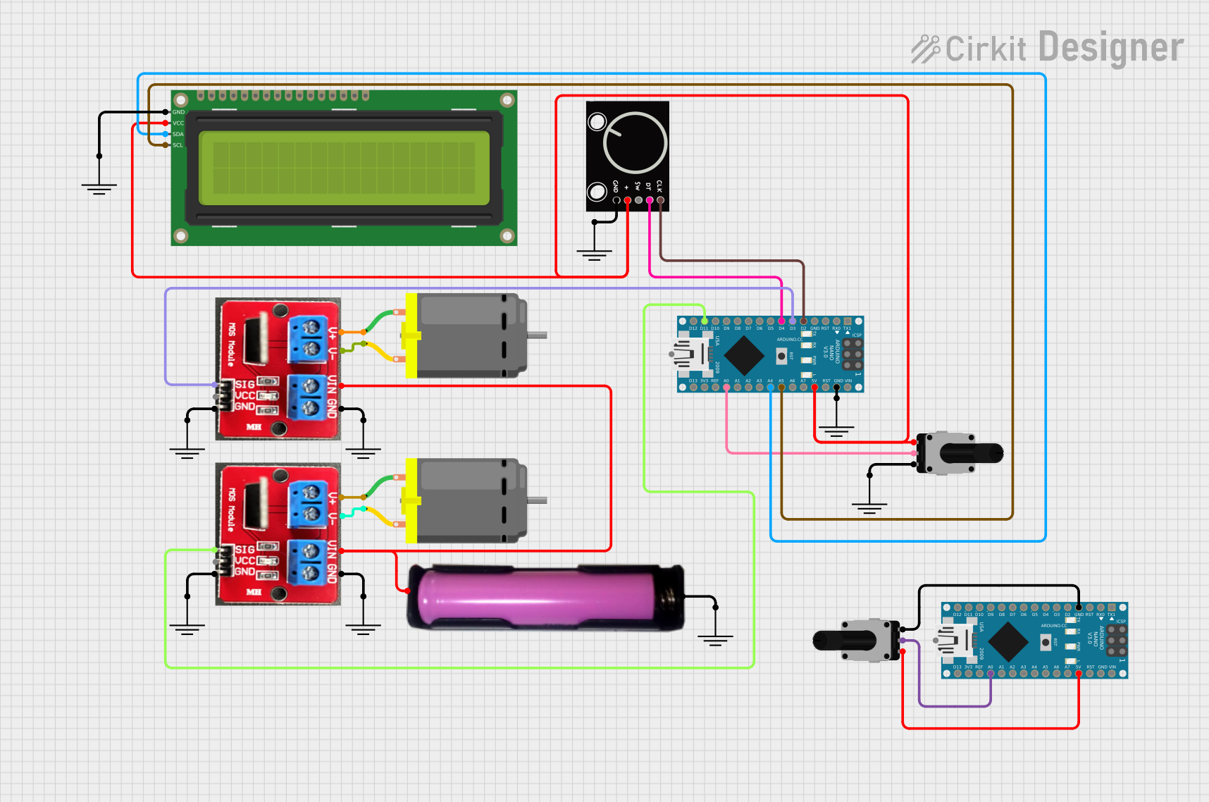
Explore Projects Built with IRF540NPBF
Common Applications
- Motor control circuits
- DC-DC converters
- Power management systems
- Switching regulators
- LED drivers
- Battery-powered systems
Technical Specifications
The IRF540NPBF is a high-performance MOSFET with the following key specifications:
| Parameter | Value |
|---|---|
| Manufacturer | Infineon Technologies |
| Part Number | IRF540NPBF |
| Type | N-Channel MOSFET |
| Maximum Drain-Source Voltage (VDS) | 100V |
| Maximum Gate-Source Voltage (VGS) | ±20V |
| Continuous Drain Current (ID) | 33A (at 25°C) |
| Pulsed Drain Current (IDM) | 110A |
| Power Dissipation (PD) | 150W |
| On-Resistance (RDS(on)) | 44mΩ (at VGS = 10V) |
| Gate Charge (Qg) | 71nC |
| Operating Temperature Range | -55°C to +175°C |
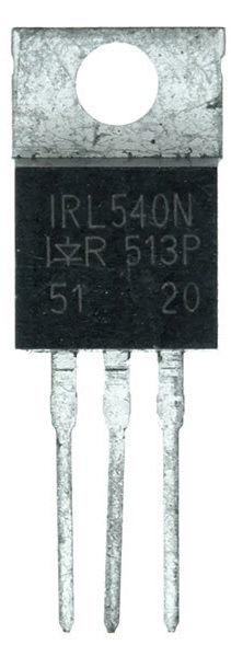
| Package Type | TO-220 |
Pin Configuration
The IRF540NPBF comes in a TO-220 package with three pins. The pin configuration is as follows:
| Pin Number | Pin Name | Description |
|---|---|---|
| 1 | Gate | Controls the MOSFET switching state |
| 2 | Drain | Current flows from drain to source |
| 3 | Source | Connected to ground or load return |
Usage Instructions
The IRF540NPBF is straightforward to use in a variety of circuits. Below are the steps and considerations for incorporating it into your design:
How to Use the IRF540NPBF in a Circuit
- Gate Control: Connect the gate pin to a control signal (e.g., from a microcontroller or driver circuit). Ensure the gate voltage (VGS) is within the specified range (typically 10V for full enhancement).
- Drain Connection: Connect the drain pin to the positive side of the load.
- Source Connection: Connect the source pin to ground or the negative side of the load.
- Gate Resistor: Use a resistor (e.g., 10Ω) between the control signal and the gate to limit inrush current and prevent oscillations.
- Flyback Diode: For inductive loads (e.g., motors), add a flyback diode across the load to protect the MOSFET from voltage spikes.
Example Circuit with Arduino UNO
The IRF540NPBF can be used to control a DC motor with an Arduino UNO. Below is an example circuit and code:
Circuit Connections
- Gate: Connect to Arduino digital pin (e.g., D9) through a 10Ω resistor.
- Drain: Connect to one terminal of the motor.
- Source: Connect to ground.
- Motor: Connect the other terminal to the positive power supply (e.g., 12V).
- Flyback Diode: Place a diode (e.g., 1N4007) across the motor terminals, with the cathode connected to the positive terminal.
Arduino Code
// IRF540NPBF MOSFET Control Example
// This code demonstrates how to control a DC motor using PWM on an Arduino UNO.

const int motorPin = 9; // Pin connected to the MOSFET gate

void setup() {
  pinMode(motorPin, OUTPUT); // Set the motor pin as an output
}

void loop() {
  analogWrite(motorPin, 128); // Set motor speed to 50% (PWM value: 128)
  delay(5000);               // Run motor for 5 seconds

  analogWrite(motorPin, 0);  // Turn off the motor
  delay(5000);               // Wait for 5 seconds
}
Important Considerations
- Ensure the gate voltage (VGS) is sufficient to fully turn on the MOSFET (10V is recommended for optimal performance).
- Use a heatsink if the MOSFET is expected to dissipate significant power.
- Avoid exceeding the maximum ratings for voltage, current, and power dissipation.
Troubleshooting and FAQs
Common Issues and Solutions
MOSFET Overheating
- Cause: Insufficient gate drive voltage or excessive current.
- Solution: Ensure VGS is at least 10V and use a heatsink if necessary.
MOSFET Not Switching
- Cause: Gate voltage too low or incorrect wiring.
- Solution: Verify the gate voltage and check all connections.
Voltage Spikes Damaging the MOSFET
- Cause: Inductive load without a flyback diode.
- Solution: Add a flyback diode across the load.
Low Efficiency
- Cause: High RDS(on) due to insufficient gate drive.
- Solution: Use a gate driver circuit to provide a higher gate voltage.
FAQs
Q: Can the IRF540NPBF be driven directly by a 5V microcontroller?
A: While the IRF540NPBF can operate with a 5V gate drive, it may not fully enhance, leading to higher RDS(on) and reduced efficiency. A gate driver or level shifter is recommended for optimal performance.
Q: Is the IRF540NPBF suitable for high-frequency switching?
A: Yes, the IRF540NPBF has a relatively low gate charge (Qg), making it suitable for high-speed switching applications.
Q: Do I need a heatsink for the IRF540NPBF?
A: A heatsink is recommended if the MOSFET is expected to dissipate significant power, especially in high-current applications.
Q: Can I use the IRF540NPBF for AC loads?
A: The IRF540NPBF is designed for DC applications. For AC loads, consider using a TRIAC or other suitable component.