Cirkit Designer Logo
Cirkit Designer
Your all-in-one circuit design IDE
Home / 
Component Documentation

How to Use Adafruit Pi Cobbler Plus: Examples, Pinouts, and Specs

Image of Adafruit Pi Cobbler Plus
Cirkit Designer LogoDesign with Adafruit Pi Cobbler Plus in Cirkit Designer

Introduction

The Adafruit Pi Cobbler Plus is a breakout board designed to facilitate the use of the GPIO (General Purpose Input/Output) pins on the Raspberry Pi. This component is essential for hobbyists, educators, and professionals who wish to interface the Raspberry Pi with various electronic circuits and sensors. The Cobbler Plus translates the Pi's GPIO pin headers to a breadboard for a more accessible and organized prototyping environment.

Explore Projects Built with Adafruit Pi Cobbler Plus

Use Cirkit Designer to design, explore, and prototype these projects online. Some projects support real-time simulation. Click "Open Project" to start designing instantly!
Raspberry Pi GPIO-Controlled LED with Resistor
Image of led_pull_up: A project utilizing Adafruit Pi Cobbler Plus in a practical application
This circuit connects a red LED to a Raspberry Pi via an Adafruit Pi Cobbler Plus. The LED is controlled through GPIO21, with a 220 Ohm resistor in series to limit the current, and the cathode of the LED is connected to ground.
Cirkit Designer LogoOpen Project in Cirkit Designer
Raspberry Pi 4B-Based Current Monitoring System with I2C OLED Display
Image of Virtual Energy Monitoring Circuit: A project utilizing Adafruit Pi Cobbler Plus in a practical application
This circuit features a Raspberry Pi 4B as the central processing unit, interfaced with an Adafruit ADS1115 16-bit I2C ADC for analog-to-digital conversion and a 0.96" OLED display for visual output. The ADS1115 is connected to a current sensor for measuring electrical current, with the sensor's output and burden pins connected to the ADC's analog input channels. The Raspberry Pi communicates with both the ADC and the OLED display over the I2C bus, using its GPIO2 and GPIO3 pins for data (SDA) and clock (SCL) lines, respectively.
Cirkit Designer LogoOpen Project in Cirkit Designer
Raspberry Pi 4B with I2C Current Sensing and OLED Display
Image of iot task 2: A project utilizing Adafruit Pi Cobbler Plus in a practical application
This circuit features a Raspberry Pi 4B as the central processing unit, interfaced with an Adafruit ADS1115 16-bit I2C ADC for analog-to-digital conversion and a 0.96" OLED display for visual output. The ADC is connected to a current sensor for measuring electrical current, with the sensor's output connected to the ADC's AIN0 pin and the burden resistor connected to AIN1. The Raspberry Pi communicates with both the ADC and the OLED display over the I2C bus, using GPIO2 (SDA) and GPIO3 (SCL) for data exchange.
Cirkit Designer LogoOpen Project in Cirkit Designer
Raspberry Pi 3B with I2C Sensor Data Acquisition and OLED Display
Image of Power Meter IoT: A project utilizing Adafruit Pi Cobbler Plus in a practical application
This circuit features a Raspberry Pi 3B as the central processing unit, interfaced with an Adafruit ADS1115 16-bit ADC for analog-to-digital conversion and a 0.96" OLED display for visual output. The ADC is connected to a current sensor for measuring electrical current, and both the ADC and OLED communicate with the Raspberry Pi via the I2C protocol. The circuit is likely used for monitoring current and displaying the measurements in real-time on the OLED screen.
Cirkit Designer LogoOpen Project in Cirkit Designer

Explore Projects Built with Adafruit Pi Cobbler Plus

Use Cirkit Designer to design, explore, and prototype these projects online. Some projects support real-time simulation. Click "Open Project" to start designing instantly!
Image of led_pull_up: A project utilizing Adafruit Pi Cobbler Plus in a practical application
Raspberry Pi GPIO-Controlled LED with Resistor
This circuit connects a red LED to a Raspberry Pi via an Adafruit Pi Cobbler Plus. The LED is controlled through GPIO21, with a 220 Ohm resistor in series to limit the current, and the cathode of the LED is connected to ground.
Cirkit Designer LogoOpen Project in Cirkit Designer
Image of Virtual Energy Monitoring Circuit: A project utilizing Adafruit Pi Cobbler Plus in a practical application
Raspberry Pi 4B-Based Current Monitoring System with I2C OLED Display
This circuit features a Raspberry Pi 4B as the central processing unit, interfaced with an Adafruit ADS1115 16-bit I2C ADC for analog-to-digital conversion and a 0.96" OLED display for visual output. The ADS1115 is connected to a current sensor for measuring electrical current, with the sensor's output and burden pins connected to the ADC's analog input channels. The Raspberry Pi communicates with both the ADC and the OLED display over the I2C bus, using its GPIO2 and GPIO3 pins for data (SDA) and clock (SCL) lines, respectively.
Cirkit Designer LogoOpen Project in Cirkit Designer
Image of iot task 2: A project utilizing Adafruit Pi Cobbler Plus in a practical application
Raspberry Pi 4B with I2C Current Sensing and OLED Display
This circuit features a Raspberry Pi 4B as the central processing unit, interfaced with an Adafruit ADS1115 16-bit I2C ADC for analog-to-digital conversion and a 0.96" OLED display for visual output. The ADC is connected to a current sensor for measuring electrical current, with the sensor's output connected to the ADC's AIN0 pin and the burden resistor connected to AIN1. The Raspberry Pi communicates with both the ADC and the OLED display over the I2C bus, using GPIO2 (SDA) and GPIO3 (SCL) for data exchange.
Cirkit Designer LogoOpen Project in Cirkit Designer
Image of Power Meter IoT: A project utilizing Adafruit Pi Cobbler Plus in a practical application
Raspberry Pi 3B with I2C Sensor Data Acquisition and OLED Display
This circuit features a Raspberry Pi 3B as the central processing unit, interfaced with an Adafruit ADS1115 16-bit ADC for analog-to-digital conversion and a 0.96" OLED display for visual output. The ADC is connected to a current sensor for measuring electrical current, and both the ADC and OLED communicate with the Raspberry Pi via the I2C protocol. The circuit is likely used for monitoring current and displaying the measurements in real-time on the OLED screen.
Cirkit Designer LogoOpen Project in Cirkit Designer

Common Applications and Use Cases

  • Prototyping Raspberry Pi projects
  • Educational purposes for learning electronics and programming
  • Interfacing with sensors, LEDs, motors, and other electronic components
  • Developing home automation systems
  • Creating IoT (Internet of Things) devices

Technical Specifications

Key Technical Details

  • Compatibility: Raspberry Pi A+, B+, Pi 2, Pi 3, Pi 4, and Pi Zero models
  • GPIO Pins: 40-pin breakout
  • Connection: 40-pin ribbon cable (included)
  • Dimensions: 63mm x 20mm x 11mm (without IDC cable)
  • Weight: 12g (without IDC cable)

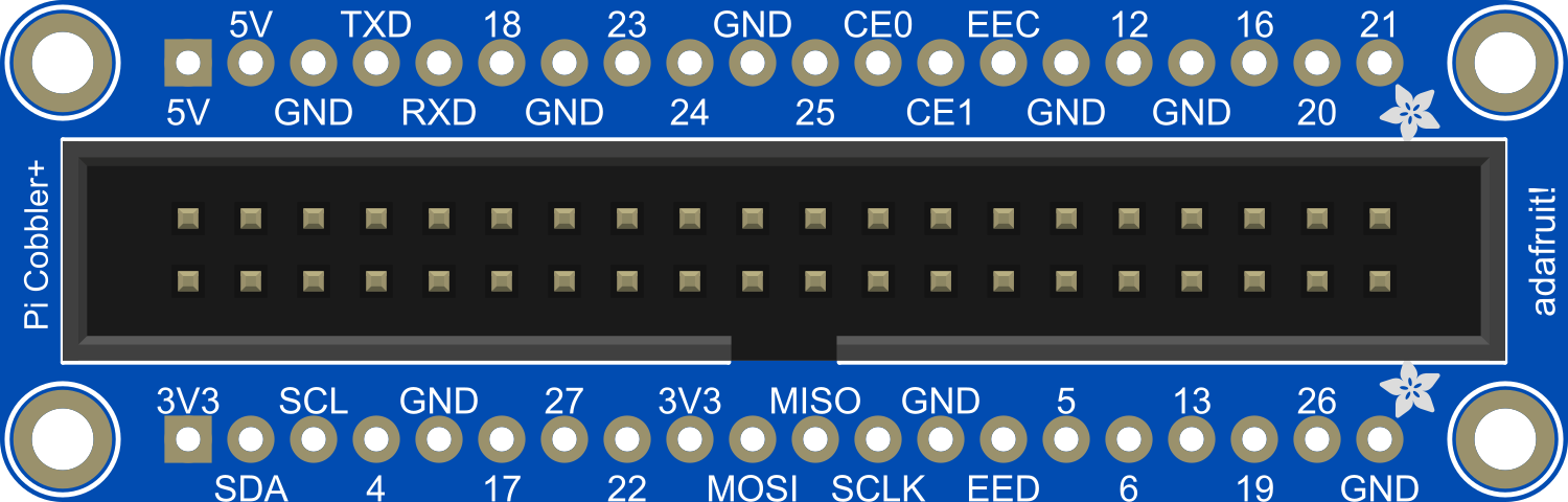
Pin Configuration and Descriptions

The following table outlines the pin configuration and descriptions for the Adafruit Pi Cobbler Plus:

Pin Number Name Description
1 3V3 3.3V Power Supply
2 5V 5V Power Supply
3 SDA I2C Data
4 5V 5V Power Supply
5 SCL I2C Clock
6 GND Ground
... ... ...
39 GND Ground
40 GPIO21 General Purpose I/O

Note: The table above is a partial representation. The full pinout can be found in the Adafruit Pi Cobbler Plus documentation or on the Adafruit website.

Usage Instructions

How to Use the Component in a Circuit

  1. Connecting to Raspberry Pi:

    • Turn off your Raspberry Pi.
    • Connect the 40-pin ribbon cable to the GPIO header on the Raspberry Pi.
    • Attach the other end of the ribbon cable to the Adafruit Pi Cobbler Plus.
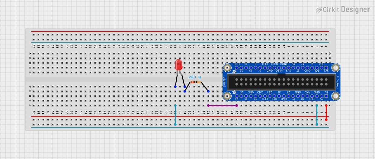
  2. Setting Up on a Breadboard:

    • Place the Cobbler Plus onto a breadboard, ensuring that the pins are securely inserted.
    • Use jumper wires to connect from the breadboard to your external components or sensors.
  3. Software Configuration:

    • Boot up your Raspberry Pi.
    • Access the terminal and ensure that the GPIO pins are configured correctly for your project.
    • Use a programming language such as Python to control the GPIO pins.

Important Considerations and Best Practices

  • Always ensure the Raspberry Pi is powered off before connecting or disconnecting the Cobbler Plus.
  • Double-check the pinout to avoid incorrect connections that could damage your Raspberry Pi or external components.
  • Use resistors where appropriate to prevent overcurrent situations.
  • Keep your firmware and software updated to ensure compatibility and security.

Troubleshooting and FAQs

Common Issues Users Might Face

  • Incorrect Pin Connections: Double-check the pinout diagram to ensure correct connections.
  • No Response from GPIO Pins: Make sure the Raspberry Pi is powered on and the pins are configured correctly in your software.
  • Damaged Ribbon Cable: Inspect the ribbon cable for any visible damage and replace if necessary.

Solutions and Tips for Troubleshooting

  • If you encounter issues, start by reviewing your circuit connections and code for any errors.
  • Consult the Raspberry Pi community forums and Adafruit support for assistance.
  • Ensure that your breadboard and jumper wires are in good condition and making proper contact.

FAQs

Q: Can I use the Cobbler Plus with any Raspberry Pi model? A: The Cobbler Plus is compatible with Raspberry Pi models that have a 40-pin GPIO header.

Q: Do I need to install any drivers to use the Cobbler Plus? A: No drivers are needed; however, you may need to enable certain interfaces like I2C or SPI via raspi-config.

Q: Can I use the Cobbler Plus for analog input? A: The Raspberry Pi does not have built-in analog input pins. You will need an external ADC (Analog-to-Digital Converter) to read analog signals.

For further assistance, refer to the Adafruit Pi Cobbler Plus guide and the Raspberry Pi GPIO documentation.