Cirkit Designer Logo
Cirkit Designer
Your all-in-one circuit design IDE
Home / 
Component Documentation

How to Use Hall Effect sensor: Examples, Pinouts, and Specs

Image of Hall Effect sensor
Cirkit Designer LogoDesign with Hall Effect sensor in Cirkit Designer

Introduction

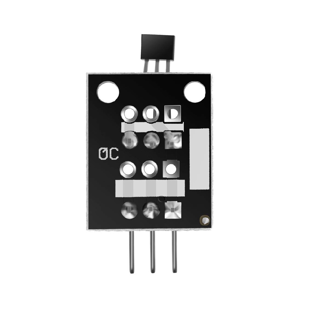
The A3144 Hall Effect sensor is a magnetic field sensor that operates based on the Hall effect principle. It detects the presence and strength of a magnetic field and outputs a digital signal accordingly. This sensor is widely used in applications requiring contactless magnetic field detection, such as proximity sensing, speed detection, and position sensing.

Explore Projects Built with Hall Effect sensor

Use Cirkit Designer to design, explore, and prototype these projects online. Some projects support real-time simulation. Click "Open Project" to start designing instantly!
Magnetic Field-Activated Solenoid Array with Arduino Control
Image of Railgun: A project utilizing Hall Effect sensor in a practical application
This circuit is designed to use Hall effect sensors for magnetic field detection, interfaced with an Arduino UNO microcontroller to control an array of solenoids through MOSFETs. It includes user interface elements such as a tactile switch and LED, and features flyback diodes for solenoid protection.
Cirkit Designer LogoOpen Project in Cirkit Designer
Arduino Nano 33 BLE Magnetic Levitation System with Hall Sensor Feedback and Status LED Indicator
Image of LEVITRON: A project utilizing Hall Effect sensor in a practical application
This circuit is designed for a magnetic levitation system that uses a Hall sensor to detect magnetic field strength and a TIP120 transistor to control the current through a levitating coil. An Arduino Nano 33 BLE microcontroller reads the sensor and adjusts the coil current via PWM to maintain levitation, while an LED indicates the system's status. The circuit includes power management with 5V DC sources and protective components like diodes and resistors for current control and indication.
Cirkit Designer LogoOpen Project in Cirkit Designer
Arduino Nano ESP32 Hall Sensor Interface with LCD Display
Image of hall effect + speedometer: A project utilizing Hall Effect sensor in a practical application
This circuit includes a Hall sensor connected to an Arduino Nano ESP32 microcontroller, which is likely used to detect magnetic fields and send the data to the microcontroller on pin D12. The Arduino is also interfaced with an LCD display, with connections for power, ground, control (RS, E), and data (DB4-DB7) to display information. The absence of code suggests that the microcontroller's behavior is not defined in this context, but it is set up to read the Hall sensor and output to the LCD.
Cirkit Designer LogoOpen Project in Cirkit Designer
Arduino Nano-Based Propeller LED Pendulum Clock with Hall Sensor and Battery Power
Image of circuit diagram: A project utilizing Hall Effect sensor in a practical application
This circuit features an Arduino Nano microcontroller interfaced with a Hall effect sensor and multiple LEDs of different colors, each paired with a resistor. The Arduino is programmed to act as a propeller LED pendulum clock, where the Hall sensor likely detects magnetic fields to synchronize the movement of the propeller, and the LEDs display time-related information. The code controls the lighting pattern of the LEDs to represent hours, minutes, and seconds, and allows for time adjustments via serial commands.
Cirkit Designer LogoOpen Project in Cirkit Designer

Explore Projects Built with Hall Effect sensor

Use Cirkit Designer to design, explore, and prototype these projects online. Some projects support real-time simulation. Click "Open Project" to start designing instantly!
Image of Railgun: A project utilizing Hall Effect sensor in a practical application
Magnetic Field-Activated Solenoid Array with Arduino Control
This circuit is designed to use Hall effect sensors for magnetic field detection, interfaced with an Arduino UNO microcontroller to control an array of solenoids through MOSFETs. It includes user interface elements such as a tactile switch and LED, and features flyback diodes for solenoid protection.
Cirkit Designer LogoOpen Project in Cirkit Designer
Image of LEVITRON: A project utilizing Hall Effect sensor in a practical application
Arduino Nano 33 BLE Magnetic Levitation System with Hall Sensor Feedback and Status LED Indicator
This circuit is designed for a magnetic levitation system that uses a Hall sensor to detect magnetic field strength and a TIP120 transistor to control the current through a levitating coil. An Arduino Nano 33 BLE microcontroller reads the sensor and adjusts the coil current via PWM to maintain levitation, while an LED indicates the system's status. The circuit includes power management with 5V DC sources and protective components like diodes and resistors for current control and indication.
Cirkit Designer LogoOpen Project in Cirkit Designer
Image of hall effect + speedometer: A project utilizing Hall Effect sensor in a practical application
Arduino Nano ESP32 Hall Sensor Interface with LCD Display
This circuit includes a Hall sensor connected to an Arduino Nano ESP32 microcontroller, which is likely used to detect magnetic fields and send the data to the microcontroller on pin D12. The Arduino is also interfaced with an LCD display, with connections for power, ground, control (RS, E), and data (DB4-DB7) to display information. The absence of code suggests that the microcontroller's behavior is not defined in this context, but it is set up to read the Hall sensor and output to the LCD.
Cirkit Designer LogoOpen Project in Cirkit Designer
Image of circuit diagram: A project utilizing Hall Effect sensor in a practical application
Arduino Nano-Based Propeller LED Pendulum Clock with Hall Sensor and Battery Power
This circuit features an Arduino Nano microcontroller interfaced with a Hall effect sensor and multiple LEDs of different colors, each paired with a resistor. The Arduino is programmed to act as a propeller LED pendulum clock, where the Hall sensor likely detects magnetic fields to synchronize the movement of the propeller, and the LEDs display time-related information. The code controls the lighting pattern of the LEDs to represent hours, minutes, and seconds, and allows for time adjustments via serial commands.
Cirkit Designer LogoOpen Project in Cirkit Designer

Common Applications and Use Cases

  • Proximity sensing: Detecting the presence of a magnetic object.
  • Speed measurement: Used in tachometers and motor speed sensors.
  • Position sensing: Determining the position of a rotating or moving object.
  • Contactless switches: Replacing mechanical switches with magnetic field detection.
  • Automotive applications: Detecting crankshaft or camshaft position in engines.

Technical Specifications

The A3144 Hall Effect sensor is a digital sensor with the following key specifications:

Parameter Value
Operating Voltage 4.5V to 24V DC
Output Type Digital (Open Collector)
Output Voltage (Low) ≤ 0.4V (at 20mA sink current)
Output Current (Sink) 25mA (maximum)
Magnetic Sensitivity Operates with a south pole magnetic field
Operating Temperature -40°C to +85°C
Package Type TO-92

Pin Configuration and Descriptions

The A3144 Hall Effect sensor has three pins, as described in the table below:

Pin Number Pin Name Description
1 VCC Power supply input (4.5V to 24V DC)
2 GND Ground connection
3 OUT Digital output signal (active low when magnetic field is detected)

Usage Instructions

How to Use the A3144 in a Circuit

  1. Power the Sensor: Connect the VCC pin to a DC voltage source (4.5V to 24V) and the GND pin to the ground of the circuit.
  2. Connect the Output: The OUT pin provides a digital signal. Use a pull-up resistor (typically 10kΩ) between the OUT pin and VCC to ensure proper operation.
  3. Place a Magnet: Position a magnet near the sensor. The sensor will output a low signal (0V) when a south pole magnetic field is detected.
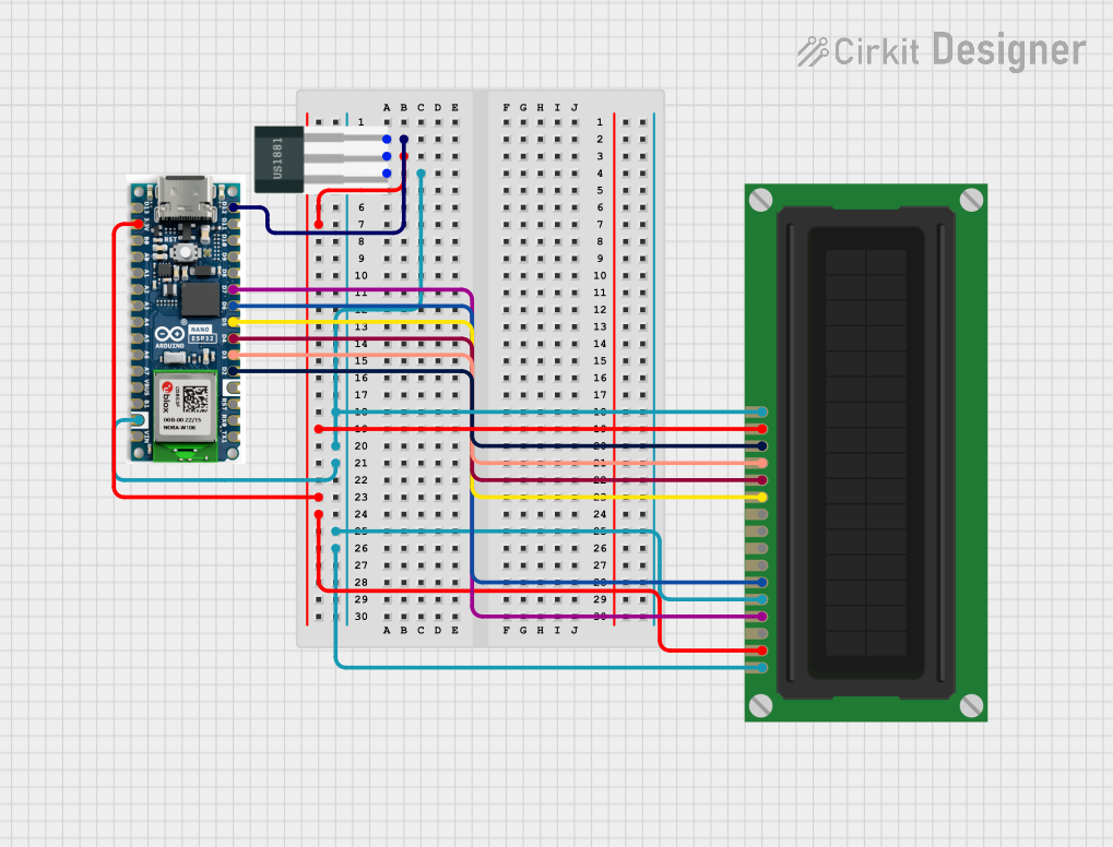
Circuit Diagram

Below is a simple circuit diagram for using the A3144 Hall Effect sensor:

VCC (5V) ----+----[10kΩ Pull-up Resistor]----+---- OUT (Digital Signal)
             |                               |
             |                               |
           A3144                           Microcontroller
             |                               |
            GND -----------------------------+

Arduino UNO Example Code

The A3144 can be easily interfaced with an Arduino UNO. Below is an example code to read the sensor's output:

// Define the pin connected to the A3144 OUT pin
const int hallSensorPin = 2; // Digital pin 2

void setup() {
  pinMode(hallSensorPin, INPUT); // Set the pin as input
  Serial.begin(9600); // Initialize serial communication
}

void loop() {
  int sensorState = digitalRead(hallSensorPin); // Read the sensor output
  
  if (sensorState == LOW) {
    // Magnetic field detected (active low output)
    Serial.println("Magnetic field detected!");
  } else {
    // No magnetic field detected
    Serial.println("No magnetic field.");
  }
  
  delay(500); // Wait for 500ms before the next reading
}

Important Considerations and Best Practices

  • Magnet Orientation: The A3144 responds to the south pole of a magnet. Ensure proper orientation for accurate detection.
  • Pull-up Resistor: Always use a pull-up resistor on the OUT pin to ensure a stable digital signal.
  • Power Supply: Use a regulated power supply within the specified voltage range to avoid damage to the sensor.
  • Distance Sensitivity: The sensor's response depends on the strength and distance of the magnetic field. Experiment with different magnets for optimal performance.

Troubleshooting and FAQs

Common Issues and Solutions

  1. No Output Signal:

    • Ensure the sensor is powered correctly (check VCC and GND connections).
    • Verify the pull-up resistor is connected between the OUT pin and VCC.
    • Check the magnet's orientation (south pole should face the sensor).
  2. Unstable or Noisy Output:

    • Use a decoupling capacitor (e.g., 0.1µF) between VCC and GND to filter noise.
    • Ensure the pull-up resistor value is appropriate (10kΩ is typical).
  3. Sensor Not Responding to Magnet:

    • Verify the magnet's strength and distance from the sensor.
    • Test with a different magnet to ensure compatibility.

FAQs

Q: Can the A3144 detect both poles of a magnet?
A: No, the A3144 is designed to detect only the south pole of a magnetic field.

Q: What is the maximum distance for magnetic field detection?
A: The detection distance depends on the strength of the magnet. Stronger magnets can be detected from a greater distance.

Q: Can I use the A3144 with a 3.3V microcontroller?
A: The A3144 requires a minimum operating voltage of 4.5V. Use a level shifter or a compatible power supply for 3.3V systems.

Q: Is the A3144 suitable for high-speed applications?
A: Yes, the A3144 has a fast response time and can be used for speed sensing applications.

By following this documentation, you can effectively integrate the A3144 Hall Effect sensor into your projects for reliable magnetic field detection.