Cirkit Designer Logo
Cirkit Designer
Your all-in-one circuit design IDE
Home / 
Component Documentation

How to Use ESP32: Examples, Pinouts, and Specs

Image of ESP32
Cirkit Designer LogoDesign with ESP32 in Cirkit Designer

Introduction

The ESP32 is a low-cost, low-power system on a chip (SoC) developed by Espressif Systems. It features integrated Wi-Fi and Bluetooth capabilities, making it an ideal choice for Internet of Things (IoT) applications. The ESP32 is highly versatile, offering dual-core processing, a wide range of GPIO pins, and support for various communication protocols. Its robust performance and energy efficiency make it suitable for smart home devices, wearable electronics, industrial automation, and more.

Explore Projects Built with ESP32

Use Cirkit Designer to design, explore, and prototype these projects online. Some projects support real-time simulation. Click "Open Project" to start designing instantly!
ESP32-Based Sensor Monitoring System with OLED Display and E-Stop
Image of MVP_design: A project utilizing ESP32 in a practical application
This circuit features an ESP32 microcontroller that interfaces with a variety of sensors and output devices. It is powered by a Lipo battery through a buck converter, ensuring a stable voltage supply. The ESP32 collects data from a DHT11 temperature and humidity sensor and a vibration sensor, controls a buzzer, and displays information on an OLED screen. An emergency stop (E Stop) is connected for safety purposes, allowing the system to be quickly deactivated.
Cirkit Designer LogoOpen Project in Cirkit Designer
ESP32-Based NTP Clock with DHT22 Temperature Sensor and WS2812 LED Matrix Display
Image of date time and temperature display : A project utilizing ESP32 in a practical application
This circuit features an ESP32 Devkit V1 microcontroller connected to a DHT22 temperature and humidity sensor and an 8x8 WS2812 RGB LED matrix. The ESP32 reads temperature data from the DHT22 sensor and displays the current date, time, and temperature on the LED matrix, with date and time synchronized via NTP (Network Time Protocol). The ESP32 provides power to both the DHT22 and the LED matrix and communicates with the DHT22 via GPIO 4 and with the LED matrix via GPIO 5.
Cirkit Designer LogoOpen Project in Cirkit Designer
ESP32-Based Environmental Monitoring System with Water Flow Sensing
Image of Water: A project utilizing ESP32 in a practical application
This circuit features an ESP32 Devkit V1 microcontroller connected to a DHT22 temperature and humidity sensor and a water flow sensor. The ESP32 reads environmental data from the DHT22 via a digital input pin (D33) and monitors water flow through the water flow sensor connected to another digital input pin (D23). The ESP32 is powered through its VIN pin, and both sensors are powered by the ESP32's 3V3 output, with common ground connections.
Cirkit Designer LogoOpen Project in Cirkit Designer
ESP32-Based Smart Weather Station with Wi-Fi Connectivity
Image of flowchart 3D: A project utilizing ESP32 in a practical application
This circuit features an ESP32 microcontroller interfacing with various sensors and modules, including a DHT22 temperature and humidity sensor, an ESP32 CAM for image capture, an I2C LCD screen for display, a load cell with an HX711 interface for weight measurement, and a buzzer for audio alerts. The ESP32 handles data acquisition, processing, and communication with these peripherals to create a multi-functional monitoring and alert system.
Cirkit Designer LogoOpen Project in Cirkit Designer

Explore Projects Built with ESP32

Use Cirkit Designer to design, explore, and prototype these projects online. Some projects support real-time simulation. Click "Open Project" to start designing instantly!
Image of MVP_design: A project utilizing ESP32 in a practical application
ESP32-Based Sensor Monitoring System with OLED Display and E-Stop
This circuit features an ESP32 microcontroller that interfaces with a variety of sensors and output devices. It is powered by a Lipo battery through a buck converter, ensuring a stable voltage supply. The ESP32 collects data from a DHT11 temperature and humidity sensor and a vibration sensor, controls a buzzer, and displays information on an OLED screen. An emergency stop (E Stop) is connected for safety purposes, allowing the system to be quickly deactivated.
Cirkit Designer LogoOpen Project in Cirkit Designer
Image of date time and temperature display : A project utilizing ESP32 in a practical application
ESP32-Based NTP Clock with DHT22 Temperature Sensor and WS2812 LED Matrix Display
This circuit features an ESP32 Devkit V1 microcontroller connected to a DHT22 temperature and humidity sensor and an 8x8 WS2812 RGB LED matrix. The ESP32 reads temperature data from the DHT22 sensor and displays the current date, time, and temperature on the LED matrix, with date and time synchronized via NTP (Network Time Protocol). The ESP32 provides power to both the DHT22 and the LED matrix and communicates with the DHT22 via GPIO 4 and with the LED matrix via GPIO 5.
Cirkit Designer LogoOpen Project in Cirkit Designer
Image of Water: A project utilizing ESP32 in a practical application
ESP32-Based Environmental Monitoring System with Water Flow Sensing
This circuit features an ESP32 Devkit V1 microcontroller connected to a DHT22 temperature and humidity sensor and a water flow sensor. The ESP32 reads environmental data from the DHT22 via a digital input pin (D33) and monitors water flow through the water flow sensor connected to another digital input pin (D23). The ESP32 is powered through its VIN pin, and both sensors are powered by the ESP32's 3V3 output, with common ground connections.
Cirkit Designer LogoOpen Project in Cirkit Designer
Image of flowchart 3D: A project utilizing ESP32 in a practical application
ESP32-Based Smart Weather Station with Wi-Fi Connectivity
This circuit features an ESP32 microcontroller interfacing with various sensors and modules, including a DHT22 temperature and humidity sensor, an ESP32 CAM for image capture, an I2C LCD screen for display, a load cell with an HX711 interface for weight measurement, and a buzzer for audio alerts. The ESP32 handles data acquisition, processing, and communication with these peripherals to create a multi-functional monitoring and alert system.
Cirkit Designer LogoOpen Project in Cirkit Designer

Common Applications

  • IoT devices and smart home systems
  • Wearable electronics
  • Wireless sensor networks
  • Industrial automation and control systems
  • Robotics and drones
  • Prototyping and development of connected devices

Technical Specifications

Key Technical Details

Specification Value
Processor Dual-core Xtensa® 32-bit LX6 microprocessor
Clock Speed Up to 240 MHz
Flash Memory 4 MB (varies by model)
SRAM 520 KB
Wi-Fi Standard 802.11 b/g/n
Bluetooth Bluetooth 4.2 and BLE
Operating Voltage 3.3V
GPIO Pins 34
ADC Channels 18 (12-bit resolution)
DAC Channels 2
Communication Interfaces UART, SPI, I2C, I2S, CAN, PWM
Power Consumption Ultra-low power modes available
Operating Temperature Range -40°C to 125°C

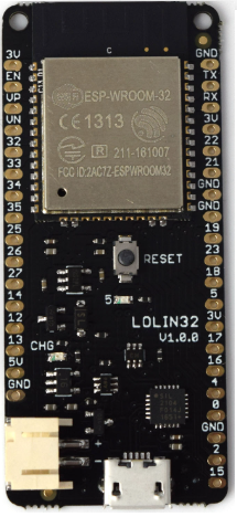
Pin Configuration and Descriptions

The ESP32 has a variety of pins for different functionalities. Below is a table summarizing the key pin configurations:

Pin Name Functionality Description
GPIO0 General Purpose I/O, Boot Mode Select Used for boot mode selection during reset
GPIO2 General Purpose I/O, ADC, Touch Can be used as ADC or capacitive touch
GPIO12 General Purpose I/O, ADC, Touch ADC input, touch sensor input
GPIO13 General Purpose I/O, PWM, ADC Supports PWM and ADC functionality
GPIO15 General Purpose I/O, ADC, Touch ADC input, touch sensor input
EN Enable Pin Active high, resets the chip when low
3V3 Power Supply 3.3V power input/output
GND Ground Ground connection
TX0/RX0 UART Communication Default UART TX/RX pins

Note: The ESP32 has multiple GPIO pins with overlapping functionalities. Refer to the datasheet for detailed pin multiplexing information.

Usage Instructions

How to Use the ESP32 in a Circuit

  1. Powering the ESP32:

    • The ESP32 operates at 3.3V. Ensure your power supply provides a stable 3.3V to the 3V3 pin.
    • Avoid supplying 5V directly to GPIO pins, as this may damage the chip.
  2. Connecting to Peripherals:

    • Use GPIO pins for connecting sensors, actuators, or other peripherals.
    • For analog inputs, connect sensors to ADC-capable GPIO pins (e.g., GPIO32 or GPIO33).
    • For communication, use UART, SPI, or I2C pins as required.
  3. Programming the ESP32:

    • The ESP32 can be programmed using the Arduino IDE or Espressif's ESP-IDF framework.
    • Connect the ESP32 to your computer via a USB-to-serial adapter or a development board with built-in USB support.
  4. Uploading Code:

    • Select the correct board and port in the Arduino IDE.
    • Press the "Upload" button to flash your code to the ESP32.

Example Code: Blinking an LED

Below is an example of how to blink an LED connected to GPIO2 using the Arduino IDE:

// Define the GPIO pin where the LED is connected
#define LED_PIN 2

void setup() {
  // Set the LED pin as an output
  pinMode(LED_PIN, OUTPUT);
}

void loop() {
  // Turn the LED on
  digitalWrite(LED_PIN, HIGH);
  delay(1000); // Wait for 1 second

  // Turn the LED off
  digitalWrite(LED_PIN, LOW);
  delay(1000); // Wait for 1 second
}

Important Considerations

  • Voltage Levels: Ensure all connected devices operate at 3.3V logic levels. Use level shifters if interfacing with 5V devices.
  • Boot Mode: GPIO0 must be pulled low during boot to enter programming mode.
  • Power Supply: Use a decoupling capacitor (e.g., 10 µF) near the power pins to stabilize the supply voltage.

Troubleshooting and FAQs

Common Issues and Solutions

  1. ESP32 Not Detected by Computer

    • Ensure the USB cable is functional and supports data transfer.
    • Install the correct USB-to-serial driver for your development board.
  2. Code Upload Fails

    • Check that the ESP32 is in programming mode (GPIO0 pulled low).
    • Verify the correct board and port are selected in the Arduino IDE.
  3. Wi-Fi Connection Issues

    • Double-check the SSID and password in your code.
    • Ensure the router is within range and supports 2.4 GHz Wi-Fi.
  4. Random Resets or Instability

    • Verify that the power supply provides sufficient current (at least 500 mA).
    • Add decoupling capacitors to stabilize the power supply.

FAQs

Q: Can the ESP32 operate on battery power?
A: Yes, the ESP32 supports ultra-low power modes, making it suitable for battery-powered applications. Use a 3.7V LiPo battery with a voltage regulator to provide 3.3V.

Q: How do I use Bluetooth on the ESP32?
A: The ESP32 supports both Bluetooth Classic and BLE. Use the BluetoothSerial library for Bluetooth Classic or the BLE library for BLE in the Arduino IDE.

Q: Can I use the ESP32 with 5V sensors?
A: Directly connecting 5V sensors to the ESP32 may damage it. Use a voltage divider or level shifter to step down the voltage to 3.3V.

Q: What is the maximum Wi-Fi range of the ESP32?
A: The ESP32's Wi-Fi range is approximately 50 meters indoors and up to 200 meters outdoors, depending on environmental conditions.

By following this documentation, you can effectively integrate the ESP32 into your projects and troubleshoot common issues.