
How to Use schneider 12V intermediate relay: Examples, Pinouts, and Specs
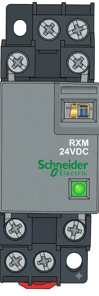
 Design with schneider 12V intermediate relay in Cirkit Designer
Introduction
The Schneider 12V Intermediate Relay (RXM2LB2BD) is a versatile electromechanical relay designed to control high-power devices using a low-power 12V DC signal. It features a compact design, multiple switching contacts, and high reliability, making it ideal for use in automation, industrial control systems, and other applications requiring electrical isolation and signal amplification.
Explore Projects Built with schneider 12V intermediate relay
 Open Project in Cirkit Designer
 Open Project in Cirkit Designer
 Open Project in Cirkit Designer
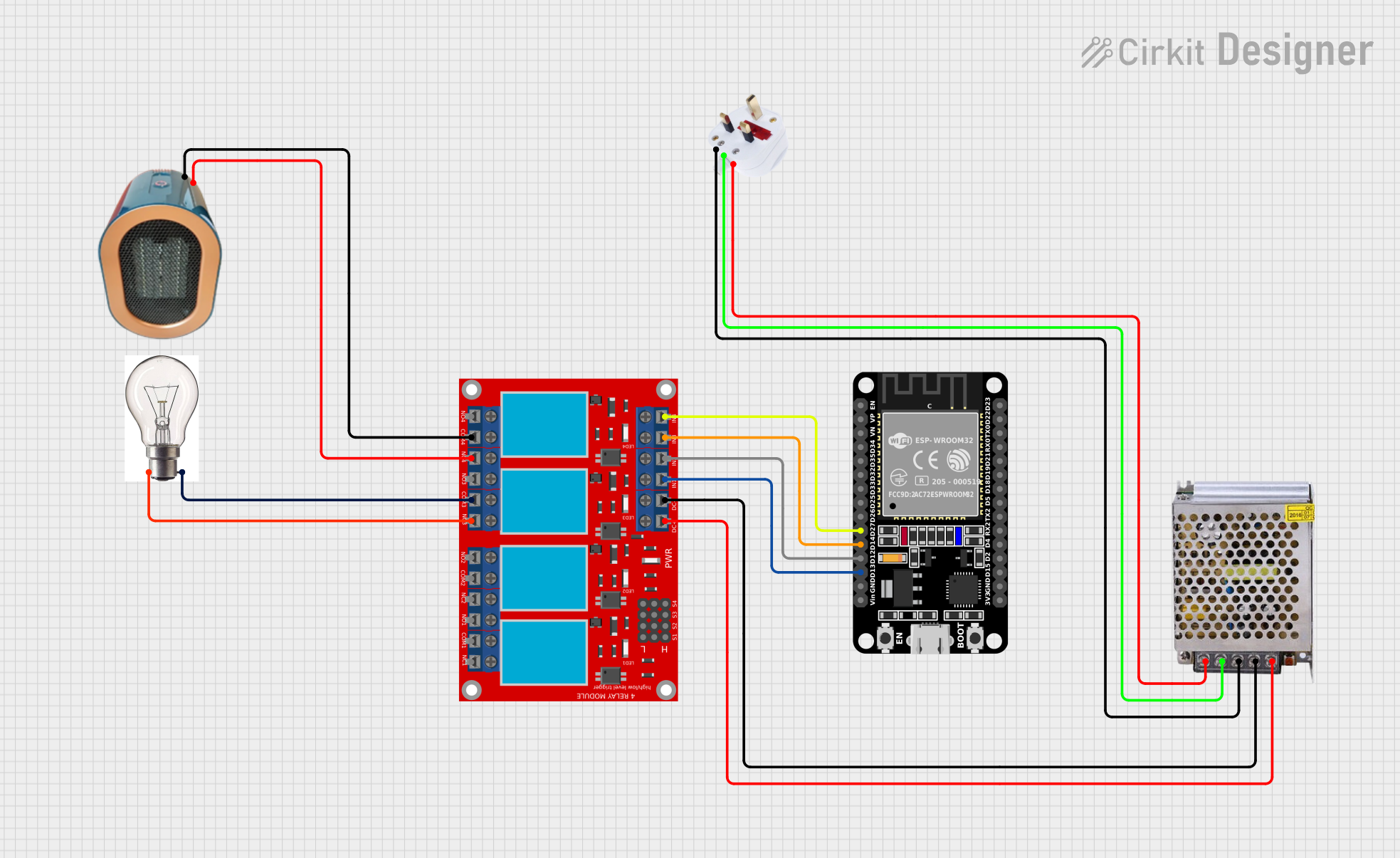 Open Project in Cirkit Designer
Explore Projects Built with schneider 12V intermediate relay
Open Project in Cirkit DesignerOpen Project in Cirkit DesignerOpen Project in Cirkit DesignerOpen Project in Cirkit DesignerCommon Applications
- Industrial automation and control systems
- Home automation circuits
- Motor control and switching
- Signal amplification and isolation
- HVAC systems
Technical Specifications
Key Technical Details
| Parameter | Value |
|---|---|
| Manufacturer | Schneider |
| Part Number | RXM2LB2BD |
| Coil Voltage | 12V DC |
| Contact Configuration | DPDT (Double Pole Double Throw) |
| Contact Rating | 10A at 250V AC / 30V DC |
| Coil Resistance | ~160 Ohms |
| Operating Temperature | -40°C to +70°C |
| Mounting Type | Plug-in (DIN rail or PCB socket) |
| Dimensions | 27mm x 21mm x 35mm |
| Insulation Resistance | ≥1000 MΩ at 500V DC |
| Dielectric Strength | 2000V AC (coil to contact) |
Pin Configuration and Descriptions
The RXM2LB2BD relay has a standard 8-pin configuration. Below is the pinout description:
| Pin Number | Description |
|---|---|
| 1 | Coil Terminal 1 (Positive) |
| 2 | Coil Terminal 2 (Negative) |
| 3 | Common Terminal for Contact Set 1 |
| 4 | Normally Closed (NC) Contact Set 1 |
| 5 | Normally Open (NO) Contact Set 1 |
| 6 | Common Terminal for Contact Set 2 |
| 7 | Normally Closed (NC) Contact Set 2 |
| 8 | Normally Open (NO) Contact Set 2 |
Usage Instructions
How to Use the Component in a Circuit
- Power the Coil: Connect a 12V DC power supply to the coil terminals (Pin 1 and Pin 2). Ensure the polarity is correct to avoid damage.
- Connect the Load:
- For each contact set, connect the load to the Common (COM) terminal (Pin 3 or Pin 6).
- Use the Normally Open (NO) terminal (Pin 5 or Pin 8) if you want the circuit to close when the relay is energized.
- Use the Normally Closed (NC) terminal (Pin 4 or Pin 7) if you want the circuit to open when the relay is energized.
- Control the Relay: Apply a 12V DC signal to the coil to activate the relay. When the coil is energized, the NO contacts close, and the NC contacts open.
Important Considerations and Best Practices
- Diode Protection: Always use a flyback diode (e.g., 1N4007) across the coil terminals to protect the driving circuit from voltage spikes caused by the collapsing magnetic field when the relay is de-energized.
- Current Rating: Ensure the load current does not exceed the relay's contact rating (10A).
- Mounting: Use a compatible DIN rail socket or PCB socket for secure mounting and easy replacement.
- Isolation: Maintain proper insulation between the coil and contact terminals to prevent electrical interference.
Example: Connecting to an Arduino UNO
The RXM2LB2BD relay can be controlled using an Arduino UNO. Below is an example circuit and code to toggle the relay:
Circuit Connections
- Connect Pin 1 of the relay to the Arduino's digital output pin (e.g., D7) through a transistor (e.g., 2N2222) and a 1kΩ base resistor.
- Connect Pin 2 of the relay to the Arduino's GND.
- Use a flyback diode (e.g., 1N4007) across Pin 1 and Pin 2 of the relay coil.
Arduino Code
// Define the relay control pin
const int relayPin = 7;

void setup() {
  // Set the relay pin as an output
  pinMode(relayPin, OUTPUT);
}

void loop() {
  // Turn the relay ON
  digitalWrite(relayPin, HIGH);
  delay(1000); // Keep the relay ON for 1 second

  // Turn the relay OFF
  digitalWrite(relayPin, LOW);
  delay(1000); // Keep the relay OFF for 1 second
}
Troubleshooting and FAQs
Common Issues and Solutions
Relay Not Activating
- Cause: Insufficient voltage or current to the coil.
- Solution: Verify that the power supply provides 12V DC and sufficient current (at least 75mA).
Contacts Not Switching
- Cause: Faulty wiring or damaged contacts.
- Solution: Double-check the wiring and ensure the load is connected to the correct terminals (COM, NO, or NC).
Voltage Spikes Damaging the Circuit
- Cause: Lack of a flyback diode across the coil.
- Solution: Install a flyback diode (e.g., 1N4007) across the coil terminals.
Overheating
- Cause: Exceeding the contact current rating.
- Solution: Ensure the load current does not exceed 10A.
FAQs
Q1: Can this relay be used with AC loads?
Yes, the RXM2LB2BD relay can switch AC loads up to 250V, provided the current does not exceed 10A.
Q2: Is the relay suitable for high-frequency switching?
No, electromechanical relays like the RXM2LB2BD are not ideal for high-frequency switching due to mechanical wear and slower response times.
Q3: Can I use this relay with a 5V control signal?
No, the RXM2LB2BD requires a 12V DC signal to activate the coil. You can use a transistor or a relay driver circuit to interface it with a 5V control signal.
Q4: How do I test if the relay is working?
Apply 12V DC to the coil terminals and listen for a clicking sound. You can also use a multimeter to check the continuity between the COM and NO/NC terminals.
This concludes the documentation for the Schneider 12V Intermediate Relay (RXM2LB2BD).