How to Use Spindle VFD: Examples, Pinouts, and Specs
Introduction
The Yaskawa J1000 Spindle Variable Frequency Drive (VFD) is a compact and efficient electronic device designed to control the speed and torque of an electric motor. By varying the frequency and voltage of the power supplied to the motor, the J1000 enables precise motor control, making it ideal for applications requiring high accuracy and reliability. This VFD is commonly used in CNC machines, conveyor systems, pumps, fans, and other industrial automation systems.
Explore Projects Built with Spindle VFD


Explore Projects Built with Spindle VFD
Common Applications
- CNC machines for spindle speed control
- Conveyor systems for adjustable speed operation
- Pumps and fans for energy-efficient motor control
- Industrial automation requiring precise motor performance
Technical Specifications
Key Technical Details
| Parameter | Specification |
|---|---|
| Manufacturer | Yaskawa |
| Model | J1000 |
| Input Voltage Range | Single-phase: 200-240V AC |
| Output Voltage Range | 0-240V AC (proportional to input) |
| Input Frequency | 50/60 Hz |
| Output Frequency Range | 0.1-400 Hz |
| Power Rating | 0.1 kW to 2.2 kW (depending on model) |
| Control Method | V/f (Voltage/Frequency) Control |
| Overload Capacity | 150% for 60 seconds |
| Operating Temperature | -10°C to 50°C |
| Communication Protocol | Modbus RTU (optional) |
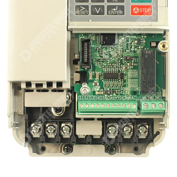
Pin Configuration and Descriptions
The Yaskawa J1000 VFD features a terminal block for control and power connections. Below is a table describing the key terminals:
Control Terminals
| Terminal Name | Function | Description |
|---|---|---|
| S1, S2, S3 | Multi-function Digital Inputs | Used for start/stop, forward/reverse, etc. |
| A1, A2 | Analog Input | Accepts 0-10V or 4-20mA for speed control |
| FM | Analog Output | Outputs frequency or current feedback |
| SC | Signal Common | Common ground for control signals |
| R+, R- | RS-485 Communication Terminals | For Modbus RTU communication (optional) |
Power Terminals
| Terminal Name | Function | Description |
|---|---|---|
| L1, L2 | AC Input Power | Connect to single-phase AC power supply |
| U, V, W | Motor Output | Connect to the motor's three-phase terminals |
| E | Earth Ground | Connect to the system ground for safety |
Usage Instructions
How to Use the Yaskawa J1000 VFD in a Circuit
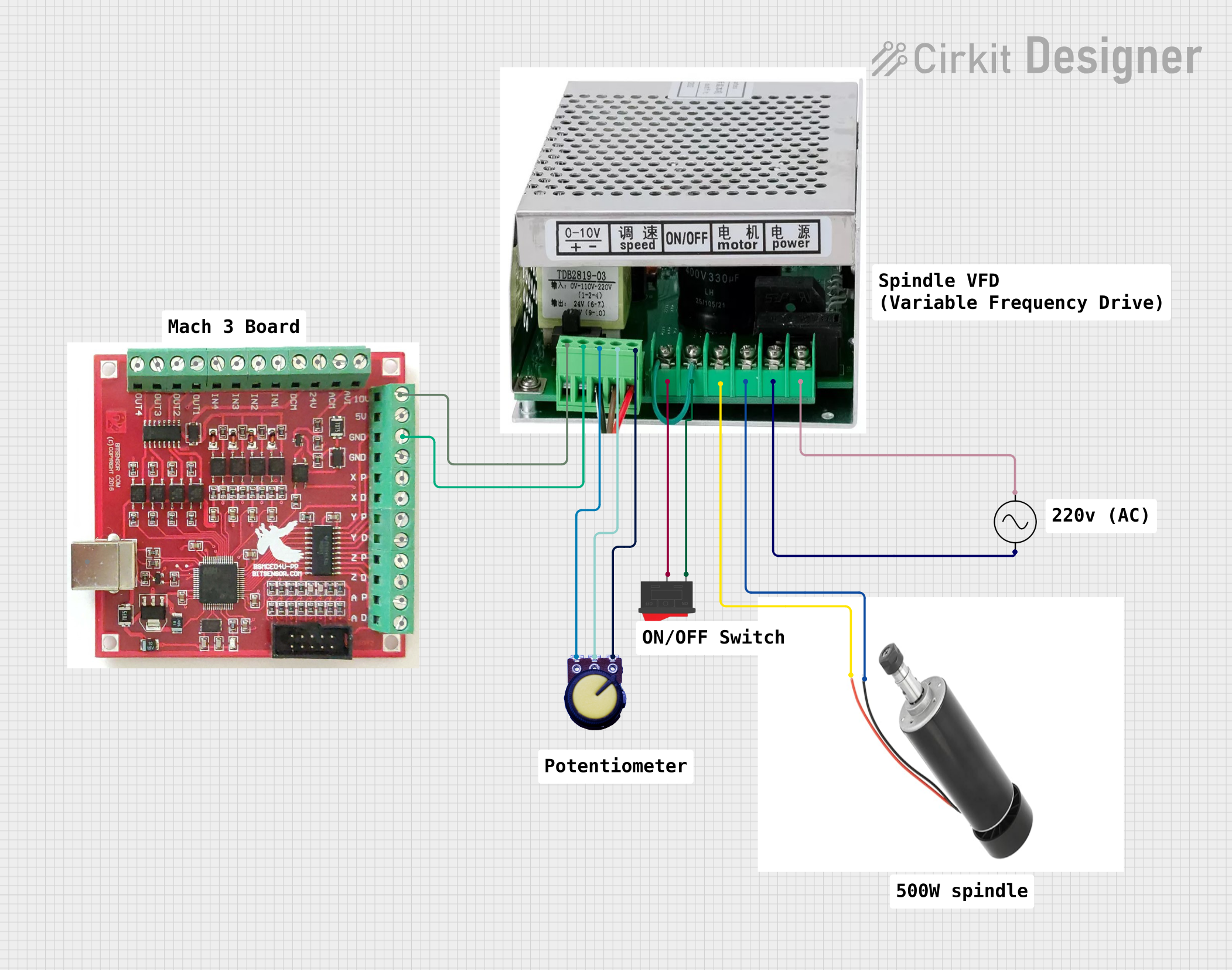
Wiring the VFD:
- Connect the AC power supply to terminals
L1andL2. - Connect the motor's three-phase terminals to
U,V, andW. - Ensure the ground terminal
Eis properly connected to the system ground. - For control, wire the start/stop switches or external controllers to the digital input terminals (
S1,S2, etc.).
- Connect the AC power supply to terminals
Configuring the VFD:
- Power on the VFD and access the parameter settings via the built-in keypad.
- Set the motor parameters (e.g., rated voltage, current, and frequency) according to the motor's datasheet.
- Configure the control mode (e.g., V/f control) and input signal type (e.g., 0-10V or 4-20mA).
Testing the System:
- Start the motor using the configured control method (e.g., digital input or analog signal).
- Gradually increase the frequency to verify smooth motor operation.
- Monitor the VFD's display for any error codes or abnormal behavior.
Important Considerations and Best Practices
- Always verify the motor's specifications before configuring the VFD.
- Use proper shielding and grounding to minimize electrical noise.
- Avoid exceeding the VFD's rated power and overload capacity.
- Regularly inspect the wiring and connections for wear or damage.
- If using Modbus RTU communication, ensure the correct baud rate and address are configured.
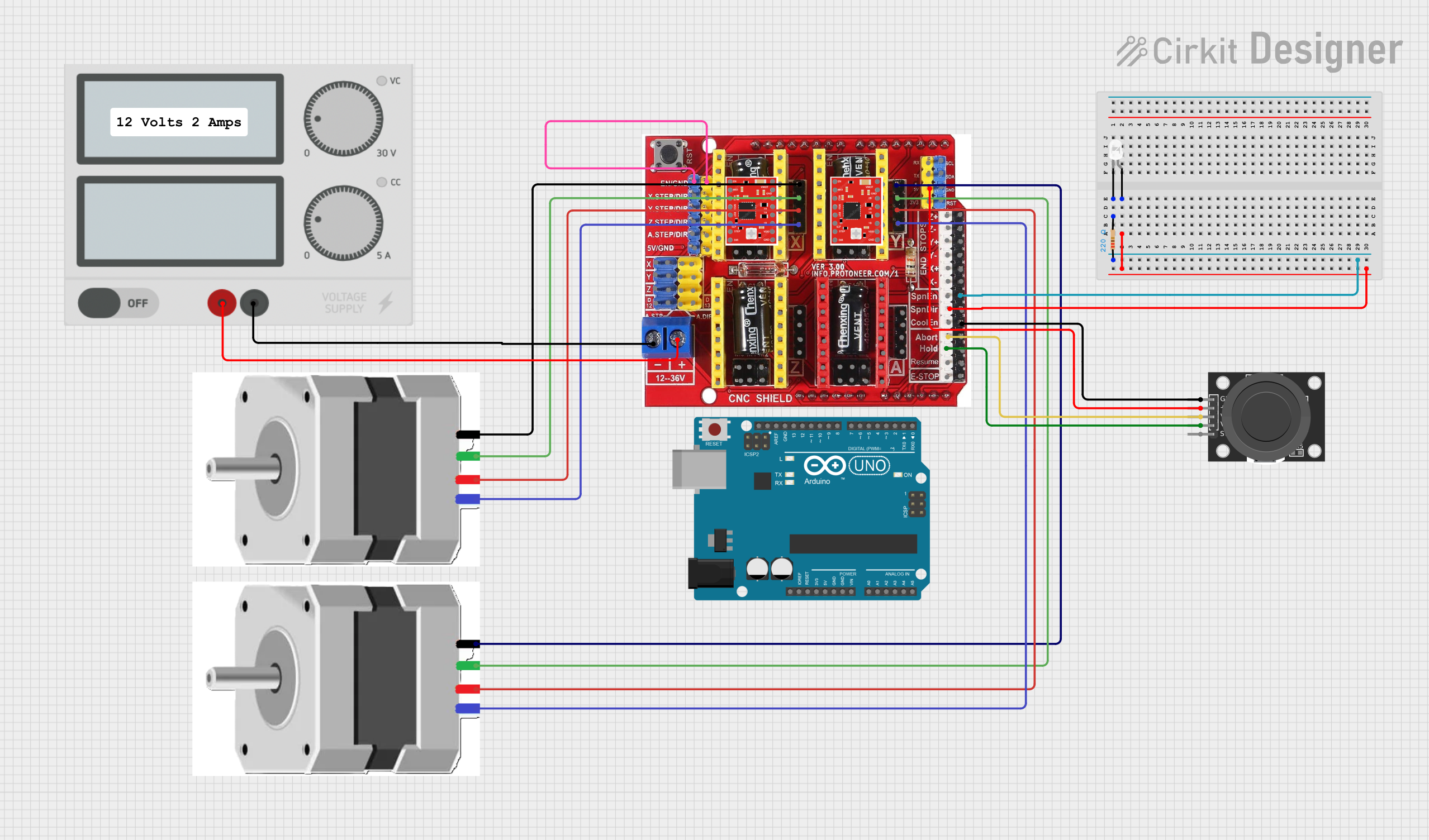
Example: Controlling the J1000 VFD with an Arduino UNO
The Yaskawa J1000 can be controlled via Modbus RTU using an Arduino UNO. Below is an example code snippet for sending a start command and setting the frequency:
#include <ModbusMaster.h>

// Instantiate ModbusMaster object
ModbusMaster node;

void setup() {
  Serial.begin(9600); // Initialize serial communication
  node.begin(1, Serial); // Set Modbus slave ID to 1

  // Send start command to VFD (write to control register)
  uint8_t result = node.writeSingleRegister(0x2000, 0x0001);
  if (result == 0) {
    Serial.println("VFD started successfully.");
  } else {
    Serial.println("Failed to start VFD.");
  }

  // Set frequency to 50 Hz (write to frequency register)
  result = node.writeSingleRegister(0x2001, 500); // Frequency in 0.1 Hz units
  if (result == 0) {
    Serial.println("Frequency set to 50 Hz.");
  } else {
    Serial.println("Failed to set frequency.");
  }
}

void loop() {
  // No continuous actions required in this example
}
Note: Ensure the Modbus communication parameters (e.g., baud rate, parity) match the VFD's settings.
Troubleshooting and FAQs
Common Issues and Solutions
VFD Does Not Start:
- Cause: Incorrect wiring or parameter settings.
- Solution: Verify all connections and ensure the start command is properly configured.
Motor Runs Erratically:
- Cause: Incorrect motor parameters or electrical noise.
- Solution: Double-check the motor's rated voltage, current, and frequency. Use shielded cables and proper grounding.
Overload or Overcurrent Error:
- Cause: Motor is drawing excessive current.
- Solution: Reduce the load on the motor or check for mechanical obstructions.
Communication Failure (Modbus RTU):
- Cause: Incorrect baud rate or wiring.
- Solution: Ensure the RS-485 connections are secure and the communication settings match.
FAQs
Q: Can the J1000 be used with a three-phase input?
A: No, the J1000 is designed for single-phase input only.Q: What is the maximum cable length for the motor connection?
A: The recommended maximum cable length is 50 meters. Use a reactor for longer distances.Q: How do I reset the VFD to factory settings?
A: Access the parameter menu and set the reset parameter (A1-03) to1.
By following this documentation, users can effectively integrate and operate the Yaskawa J1000 Spindle VFD in their applications.