How to Use AD620: Examples, Pinouts, and Specs
AD620 Instrumentation Amplifier Documentation
1. Introduction
The AD620 is a low-power instrumentation amplifier renowned for its high accuracy and low noise characteristics. It is designed to amplify small differential signals while rejecting large common-mode voltages, making it particularly suitable for applications in sensor interfacing and medical instrumentation. The AD620's high common-mode rejection ratio (CMRR) ensures that it can effectively process signals in noisy environments, which is critical for precision measurements.
Common Applications and Use Cases
- Medical Instrumentation: Used in ECG, EEG, and other bio-signal amplifiers.
- Sensor Applications: Ideal for amplifying signals from thermocouples, strain gauges, and pressure sensors.
- Industrial Automation: Employed in data acquisition systems and process control.
- Consumer Electronics: Utilized in audio equipment and portable devices for signal conditioning.
2. Technical Specifications
Key Technical Details
| Parameter | Value |
|---|---|
| Supply Voltage (V+) | +2.3V to +18V |
| Supply Voltage (V-) | -2.3V to -18V |
| Input Voltage Range | ±0.1V to ±0.5V |
| Gain Range | 1 to 1000 |
| Input Bias Current | 1 pA (typical) |
| Common-Mode Rejection Ratio | 120 dB (typical) |
| Noise (Input Voltage) | 0.1 µV (typical) |
| Power Consumption | 1.2 mW (typical) |
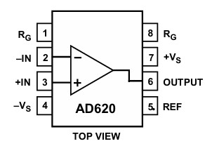
Pin Configuration and Descriptions
| Pin Number | Pin Name | Description |
|---|---|---|
| 1 | V- | Negative power supply connection |
| 2 | V+ | Positive power supply connection |
| 3 | RGain | Gain resistor connection (external resistor) |
| 4 | Ref | Reference voltage input (for offset adjustment) |
| 5 | IN+ | Non-inverting input for the differential signal |
| 6 | IN- | Inverting input for the differential signal |
| 7 | OUT | Output signal (amplified differential signal) |
| 8 | NC | No connection (not used) |
3. Usage Instructions
How to Use the AD620 in a Circuit
Power Supply Connection:
- Connect the V+ pin to a positive voltage supply (between +2.3V and +18V).
- Connect the V- pin to a negative voltage supply (between -2.3V and -18V).
Input Signal Connection:
- Connect the differential input signals to the IN+ and IN- pins.
- Ensure that the input voltage range is within ±0.1V to ±0.5V.
Gain Configuration:
- To set the gain, connect a resistor (RGain) between the RGain pin and the ground. The gain can be calculated using the formula: [ \text{Gain} = 1 + \frac{49.4k\Omega}{R_{Gain}} ]
Reference Voltage:
- If needed, connect a reference voltage to the Ref pin to adjust the output offset.
Output Signal:
- The amplified output can be taken from the OUT pin.
Important Considerations and Best Practices
- Ensure proper decoupling of the power supply to minimize noise.
- Use twisted pair cables for input signals to reduce interference.
- Keep the gain resistor (RGain) as close to the AD620 as possible to minimize parasitic capacitance.
- If using in a noisy environment, consider shielding the circuit.
4. Troubleshooting and FAQs
Common Issues Users Might Face
No Output Signal:
- Check power supply connections (V+ and V-).
- Ensure that the input signals are within the specified range.
Distorted Output:
- Verify the gain setting and ensure the input signals are not saturating the amplifier.
- Check for any ground loops or interference in the circuit.
Excessive Noise:
- Ensure proper decoupling of the power supply.
- Use shielded cables for input connections.
Solutions and Tips for Troubleshooting
- Always refer to the datasheet for detailed specifications and application notes.
- Use an oscilloscope to monitor the input and output signals for better diagnosis.
- If using in a sensitive application, consider implementing additional filtering on the output.
Example Arduino Code
If you are interfacing the AD620 with an Arduino UNO, you can use the following code to read the output signal:
const int analogPin = A0; // Pin connected to AD620 output
void setup() {
  Serial.begin(9600); // Initialize serial communication
}

void loop() {
  int sensorValue = analogRead(analogPin); // Read the output
  float voltage = sensorValue * (5.0 / 1023.0); // Convert to voltage
  Serial.print("Output Voltage: ");
  Serial.println(voltage); // Print the voltage value
  delay(1000); // Wait for a second
}
This code reads the output voltage from the AD620 and prints it to the serial monitor. Make sure to adjust the analog pin according to your circuit configuration.
Explore Projects Built with AD620
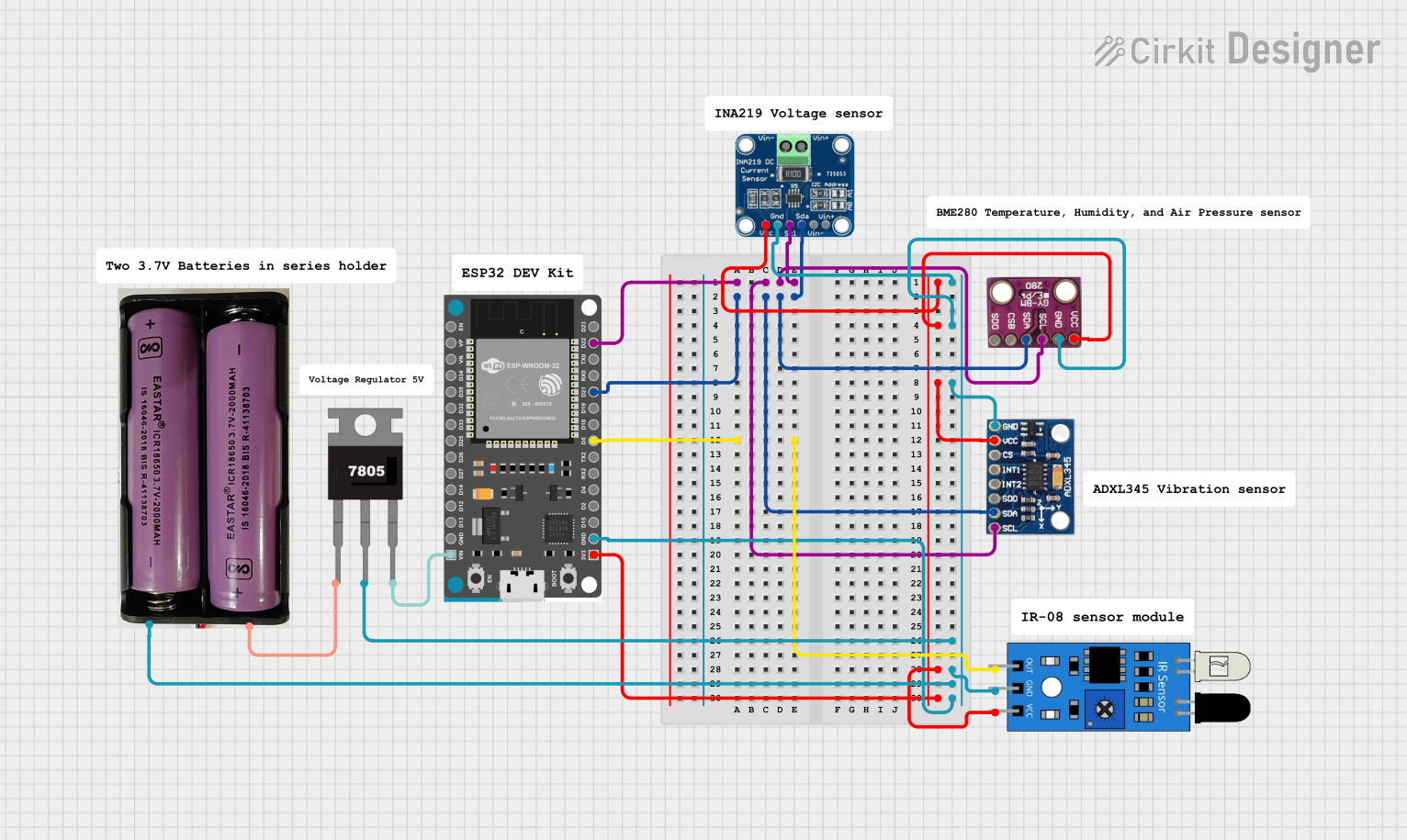

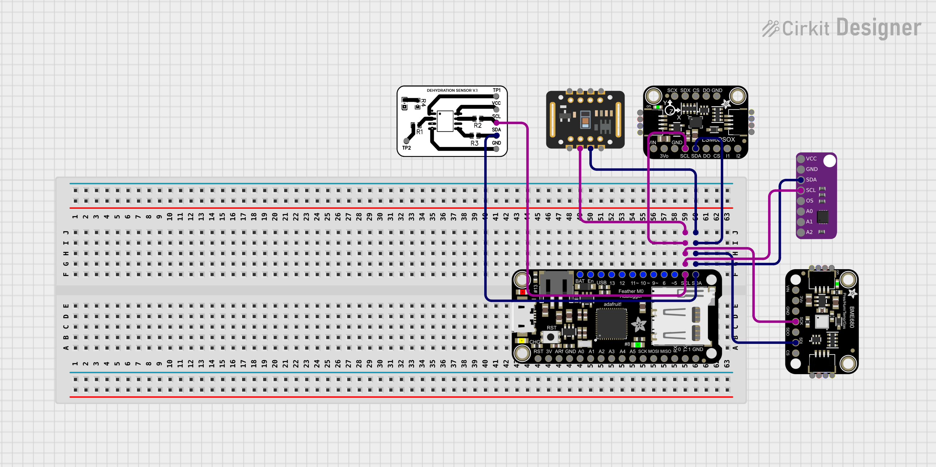
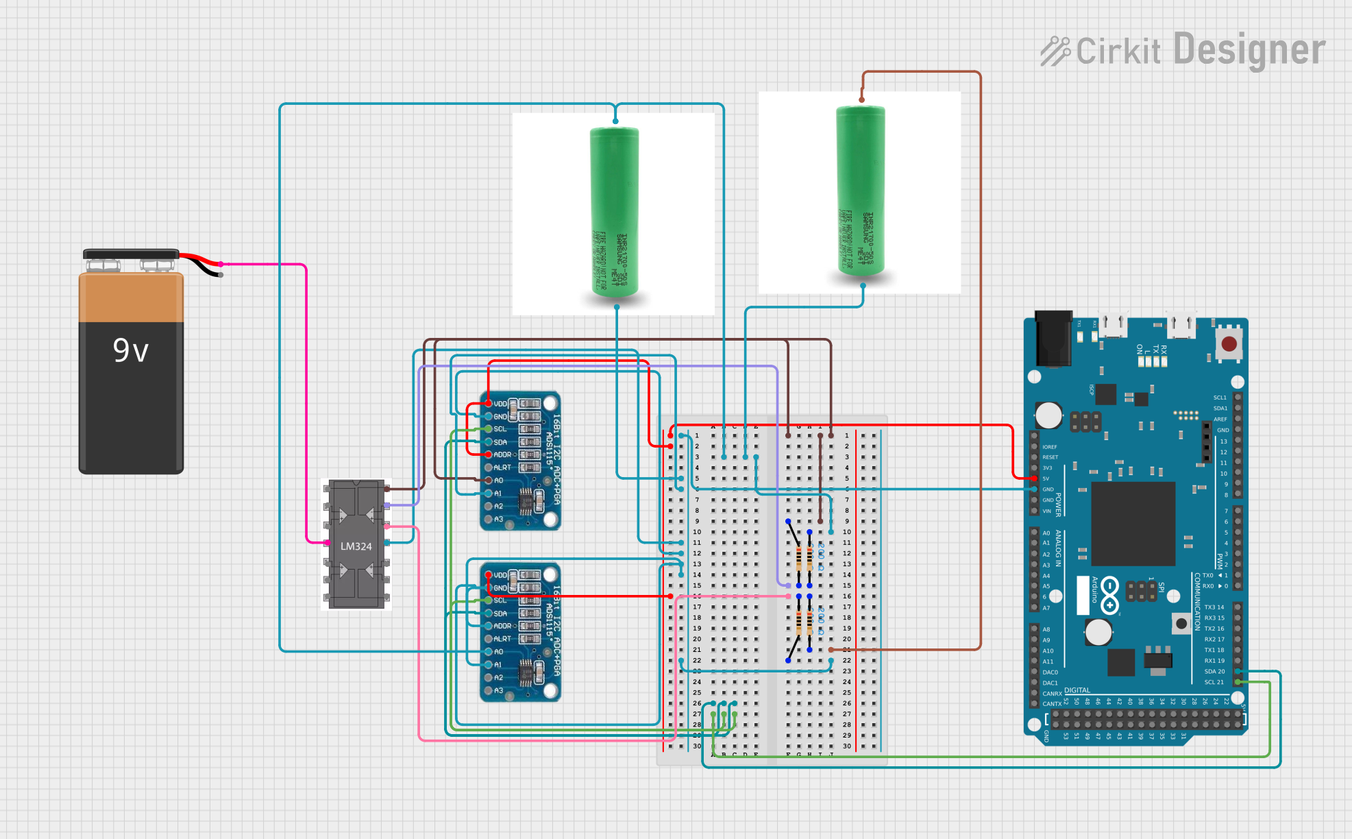
Explore Projects Built with AD620