How to Use XY-LPWM: Examples, Pinouts, and Specs
Introduction
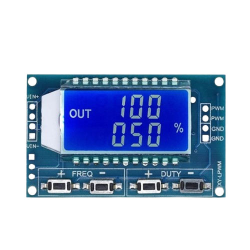
The XY-LPWM is a versatile PWM (Pulse Width Modulation) controller module designed for controlling the speed of DC motors, the brightness of LEDs, and other applications requiring precise power management. By adjusting the duty cycle of the PWM signal, the module enables efficient control of connected devices without significant energy loss. Its compact design and ease of use make it a popular choice for hobbyists and professionals alike.
Explore Projects Built with XY-LPWM
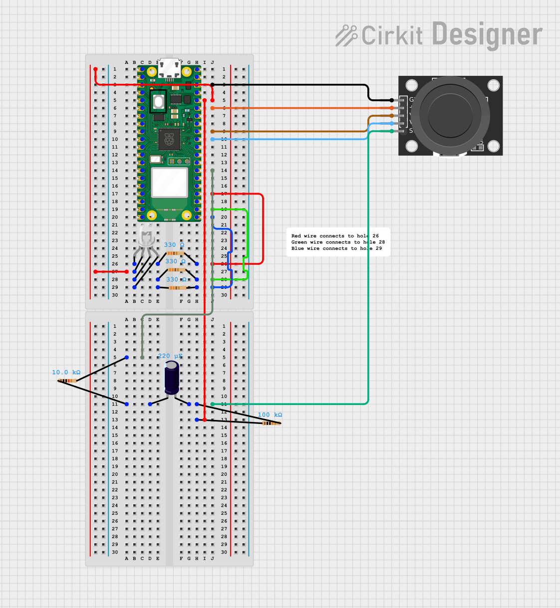
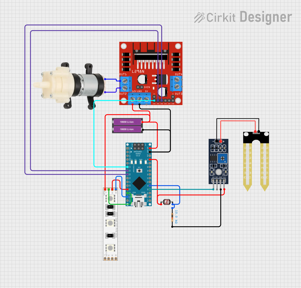
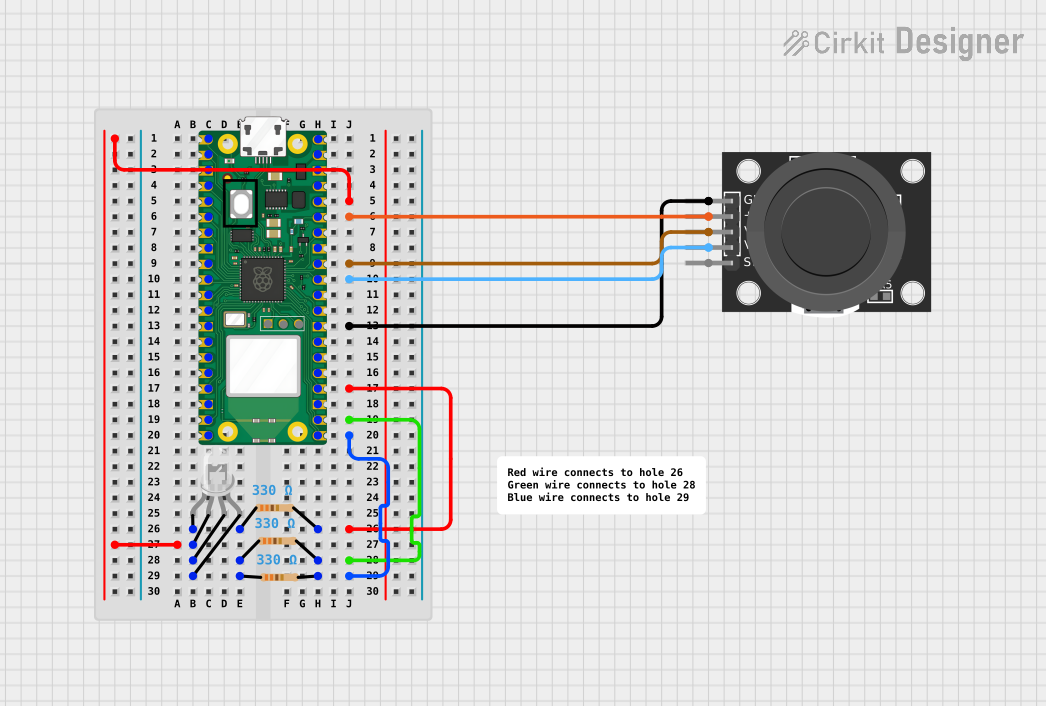

Explore Projects Built with XY-LPWM
Common Applications
- Speed control of DC motors in robotics and automation projects
- Brightness adjustment of LED lighting systems
- Power regulation in heating elements
- Signal generation for testing and prototyping circuits
- General-purpose PWM control in DIY electronics projects
Technical Specifications
Below are the key technical details of the XY-LPWM module:
| Parameter | Specification |
|---|---|
| Input Voltage Range | 5V to 30V DC |
| Output Voltage Range | 0V to Input Voltage |
| Output Current | Up to 5A |
| PWM Frequency | 1 kHz to 150 kHz (adjustable) |
| Duty Cycle Range | 0% to 100% |
| Control Interface | Potentiometer for duty cycle control |
| Dimensions | 48mm x 24mm x 11mm |
Pin Configuration and Descriptions
The XY-LPWM module typically has the following pin layout:
| Pin Name | Description |
|---|---|
| VIN | Positive input voltage terminal (5V to 30V DC) |
| GND | Ground terminal for input voltage |
| VOUT | Positive output voltage terminal (PWM-controlled output) |
| GND | Ground terminal for output voltage |
Usage Instructions
How to Use the XY-LPWM in a Circuit
- Power the Module: Connect the VIN and GND pins to a DC power source within the specified voltage range (5V to 30V).
- Connect the Load: Attach the device you want to control (e.g., motor or LED) to the VOUT and GND output terminals.
- Adjust the Duty Cycle: Use the onboard potentiometer to adjust the duty cycle of the PWM signal. Turning the potentiometer clockwise increases the duty cycle, while turning it counterclockwise decreases it.
- Fine-Tune the Frequency: If your module supports frequency adjustment, use the designated trimmer or jumper to set the desired PWM frequency.
Important Considerations
- Ensure the input voltage does not exceed the module's maximum rating of 30V to avoid damage.
- The output current should not exceed 5A. Use a heatsink or active cooling if operating near the maximum current for extended periods.
- For inductive loads like motors, consider adding a flyback diode across the load to protect the module from voltage spikes.
- If using the module with an Arduino UNO or other microcontroller, ensure the PWM signal generated by the microcontroller matches the module's input requirements.
Example: Controlling an LED with Arduino UNO
The XY-LPWM module can be used with an Arduino UNO to control the brightness of an LED. Below is an example code snippet:
// Example: Controlling LED brightness using Arduino and XY-LPWM module
// Connect the Arduino PWM pin (e.g., D9) to the VIN pin of the XY-LPWM module.
// Connect the LED to the VOUT pin of the XY-LPWM module.

int pwmPin = 9; // Define the PWM pin on Arduino

void setup() {
  pinMode(pwmPin, OUTPUT); // Set the PWM pin as an output
}

void loop() {
  for (int dutyCycle = 0; dutyCycle <= 255; dutyCycle++) {
    analogWrite(pwmPin, dutyCycle); // Gradually increase brightness
    delay(10); // Small delay for smooth transition
  }
  for (int dutyCycle = 255; dutyCycle >= 0; dutyCycle--) {
    analogWrite(pwmPin, dutyCycle); // Gradually decrease brightness
    delay(10); // Small delay for smooth transition
  }
}
Troubleshooting and FAQs
Common Issues
No Output Voltage:
- Ensure the input voltage is within the specified range (5V to 30V).
- Verify that the load is properly connected to the VOUT and GND terminals.
- Check if the potentiometer is set to a non-zero duty cycle.
Overheating:
- Ensure the output current does not exceed 5A.
- Use a heatsink or active cooling if operating near the maximum current.
PWM Signal Not Working with Microcontroller:
- Confirm that the microcontroller's PWM frequency is compatible with the XY-LPWM module.
- Check the wiring between the microcontroller and the module.
FAQs
Q: Can the XY-LPWM module be used with AC loads?
A: No, the XY-LPWM module is designed for DC loads only. Using it with AC loads may damage the module.
Q: How do I adjust the PWM frequency?
A: Some versions of the XY-LPWM module include a trimmer or jumper for frequency adjustment. Refer to the specific module's datasheet for detailed instructions.
Q: Can I use the module to control multiple devices simultaneously?
A: Yes, as long as the total current drawn by the devices does not exceed 5A. Ensure proper wiring and cooling for stable operation.
Q: Is the module compatible with 3.3V microcontrollers?
A: The module's input voltage range starts at 5V, so it may not work directly with 3.3V microcontrollers. Use a level shifter or a 5V power source for compatibility.