How to Use max3232: Examples, Pinouts, and Specs
Introduction
The MAX3232 is a dual RS-232 transceiver designed to convert signals between TTL/CMOS logic levels and RS-232 levels. It operates over a wide voltage range of 3V to 5.5V, making it suitable for modern low-power systems. The device is commonly used in serial communication applications, such as interfacing microcontrollers with RS-232 devices like computers, modems, or other serial peripherals.
Explore Projects Built with max3232


Explore Projects Built with max3232
Common Applications and Use Cases
- Serial communication between microcontrollers and PCs
- Interfacing with RS-232-compatible devices (e.g., modems, printers)
- Embedded systems requiring RS-232 communication
- Data logging and debugging tools
Technical Specifications
Key Technical Details
- Operating Voltage: 3.0V to 5.5V
- RS-232 Output Voltage Levels: ±5V to ±15V
- Data Rate: Up to 250 kbps
- Number of Drivers/Receivers: 2 drivers, 2 receivers
- Low Power Consumption: 1 µA in shutdown mode
- Capacitor Requirements: Requires four external capacitors (0.1 µF typical)
- Temperature Range: -40°C to +85°C (industrial grade)
Pin Configuration and Descriptions
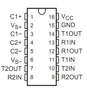
The MAX3232 is typically available in a 16-pin SOIC or TSSOP package. Below is the pinout and description:
| Pin Number | Pin Name | Description |
|---|---|---|
| 1 | C1+ | Positive terminal of the charge pump capacitor 1 |
| 2 | V+ | Positive voltage generated by the charge pump |
| 3 | C1- | Negative terminal of the charge pump capacitor 1 |
| 4 | C2+ | Positive terminal of the charge pump capacitor 2 |
| 5 | C2- | Negative terminal of the charge pump capacitor 2 |
| 6 | V- | Negative voltage generated by the charge pump |
| 7 | T2OUT | Transmitter 2 output (RS-232 level) |
| 8 | R2IN | Receiver 2 input (RS-232 level) |
| 9 | R2OUT | Receiver 2 output (TTL/CMOS level) |
| 10 | T2IN | Transmitter 2 input (TTL/CMOS level) |
| 11 | T1IN | Transmitter 1 input (TTL/CMOS level) |
| 12 | R1OUT | Receiver 1 output (TTL/CMOS level) |
| 13 | R1IN | Receiver 1 input (RS-232 level) |
| 14 | T1OUT | Transmitter 1 output (RS-232 level) |
| 15 | GND | Ground |
| 16 | VCC | Power supply input (3.0V to 5.5V) |
Usage Instructions
How to Use the MAX3232 in a Circuit
- Power Supply: Connect the VCC pin to a 3.0V to 5.5V power source and the GND pin to ground.
- External Capacitors: Connect four external capacitors (typically 0.1 µF) to the charge pump pins (C1+, C1-, C2+, C2-, V+, and V-). Refer to the datasheet for the recommended capacitor configuration.
- RS-232 Connections:
- Connect the T1OUT and T2OUT pins to the RS-232 device's RX pins.
- Connect the R1IN and R2IN pins to the RS-232 device's TX pins.
- TTL/CMOS Connections:
- Connect the T1IN and T2IN pins to the microcontroller's TX pins.
- Connect the R1OUT and R2OUT pins to the microcontroller's RX pins.
- Bypass Capacitor: Place a 0.1 µF decoupling capacitor close to the VCC pin to reduce noise.
Important Considerations and Best Practices
- Ensure the external capacitors are of the correct value and placed as close as possible to the MAX3232.
- Avoid exceeding the maximum voltage ratings to prevent damage to the device.
- Use proper grounding techniques to minimize noise in the circuit.
- Verify the RS-232 and TTL/CMOS voltage levels are compatible with the connected devices.
Example: Connecting MAX3232 to an Arduino UNO
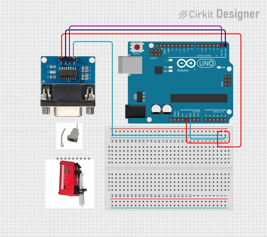
Below is an example of how to connect the MAX3232 to an Arduino UNO for serial communication with an RS-232 device.
Circuit Diagram
- Connect the MAX3232's T1IN to the Arduino's TX pin (D1).
- Connect the MAX3232's R1OUT to the Arduino's RX pin (D0).
- Connect the RS-232 device's RX pin to T1OUT and its TX pin to R1IN.
- Add the required external capacitors as per the datasheet.
Arduino Code Example
// Example code for using MAX3232 with Arduino UNO
// This code sends and receives data over RS-232 using the MAX3232 transceiver.

void setup() {
  Serial.begin(9600); // Initialize serial communication at 9600 baud
  Serial.println("MAX3232 RS-232 Communication Initialized");
}

void loop() {
  // Check if data is available from the RS-232 device
  if (Serial.available() > 0) {
    char receivedData = Serial.read(); // Read the incoming data
    Serial.print("Received: ");
    Serial.println(receivedData); // Print the received data
  }

  // Send data to the RS-232 device
  Serial.println("Hello from Arduino!"); // Send a test message
  delay(1000); // Wait for 1 second
}
Troubleshooting and FAQs
Common Issues and Solutions
No Communication Between Devices:
- Verify the connections between the MAX3232, microcontroller, and RS-232 device.
- Ensure the external capacitors are correctly connected and of the recommended value.
- Check the baud rate settings of both devices to ensure they match.
Data Corruption:
- Ensure proper grounding between all devices in the circuit.
- Use shielded cables for RS-232 connections to reduce noise.
Device Overheating:
- Verify the supply voltage is within the 3.0V to 5.5V range.
- Check for short circuits or incorrect wiring.
No Output on RS-232 Side:
- Confirm that the T1IN and T2IN pins are receiving valid TTL/CMOS signals.
- Check the charge pump capacitors for proper operation.
FAQs
Q1: Can I use the MAX3232 with a 5V microcontroller?
Yes, the MAX3232 supports a supply voltage range of 3.0V to 5.5V, making it compatible with 5V microcontrollers.
Q2: What is the maximum cable length for RS-232 communication?
The RS-232 standard supports cable lengths up to 15 meters (50 feet) at lower baud rates. However, shorter cables are recommended for higher baud rates to reduce signal degradation.
Q3: Can I use different capacitor values for the charge pump?
It is recommended to use 0.1 µF capacitors as specified in the datasheet. Using different values may affect the performance of the charge pump.
Q4: Is the MAX3232 compatible with 1.8V logic levels?
No, the MAX3232 requires a minimum supply voltage of 3.0V. For 1.8V systems, consider using a level shifter or a different transceiver designed for lower voltages.