
How to Use MIC4576 (TO263): Examples, Pinouts, and Specs
 Design with MIC4576 (TO263) in Cirkit Designer
Introduction
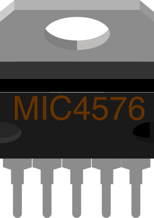
The MIC4576 is a high-efficiency step-down (buck) switching regulator manufactured by Microchip Technology. It is capable of delivering up to 1.5A of output current, making it suitable for a wide range of power supply applications. The regulator operates with a wide input voltage range of 4V to 60V, ensuring compatibility with various power sources. Its low quiescent current and high efficiency make it ideal for battery-powered systems. The TO263 package provides excellent thermal performance, allowing the component to operate reliably under demanding conditions.
Explore Projects Built with MIC4576 (TO263)
 Open Project in Cirkit Designer
 Open Project in Cirkit Designer
 Open Project in Cirkit Designer
 Open Project in Cirkit Designer
Explore Projects Built with MIC4576 (TO263)
Open Project in Cirkit DesignerOpen Project in Cirkit DesignerOpen Project in Cirkit DesignerOpen Project in Cirkit DesignerCommon Applications
- DC-DC converters for industrial and automotive systems
- Battery-powered devices
- Distributed power systems
- Embedded systems requiring efficient voltage regulation
- LED drivers and low-noise power supplies
Technical Specifications
Key Specifications
| Parameter | Value |
|---|---|
| Input Voltage Range | 4V to 60V |
| Output Voltage Range | 1.23V to 57V |
| Maximum Output Current | 1.5A |
| Efficiency | Up to 90% |
| Switching Frequency | 200 kHz (typical) |
| Quiescent Current | 5mA (typical) |
| Operating Temperature Range | -40°C to +125°C |
| Package Type | TO263-5L |
Pin Configuration
The MIC4576 in the TO263 package has 5 pins. The table below describes each pin:
| Pin Number | Pin Name | Description |
|---|---|---|
| 1 | VIN | Input voltage supply. Connect to the unregulated DC input voltage source. |
| 2 | GND | Ground. Connect to the system ground. |
| 3 | SW | Switch output. Connect to the inductor and diode in the output circuit. |
| 4 | FB | Feedback input. Connect to a resistor divider to set the output voltage. |
| 5 | EN (Enable) | Enable input. Pull high to enable the regulator, or low to disable it. |
Usage Instructions
Using the MIC4576 in a Circuit
- Input Voltage Supply: Connect the VIN pin to a DC voltage source within the range of 4V to 60V. Ensure the input voltage is higher than the desired output voltage.
- Output Voltage Setting: Use a resistor divider network connected to the FB pin to set the desired output voltage. The output voltage can be calculated using the formula: [ V_{OUT} = 1.23 \times \left(1 + \frac{R1}{R2}\right) ] where R1 and R2 are the resistors in the divider network.
- Inductor and Diode Selection: Choose an inductor and a Schottky diode rated for the desired output current and voltage. Ensure the inductor value provides stable operation at the switching frequency.
- Output Capacitor: Use a low-ESR capacitor at the output to minimize voltage ripple. A typical value is 100µF.
- Enable Pin: Pull the EN pin high to enable the regulator. If unused, connect it to VIN through a pull-up resistor.
- Thermal Considerations: Ensure adequate heat dissipation by mounting the TO263 package on a PCB with sufficient copper area or using a heatsink if necessary.
Example Circuit with Arduino UNO
The MIC4576 can be used to power an Arduino UNO by stepping down a higher voltage (e.g., 12V) to 5V. Below is an example circuit and Arduino code to monitor the output voltage.
Circuit Diagram
- Connect a 12V DC source to the VIN pin.
- Set the output voltage to 5V using a resistor divider (e.g., R1 = 3.9kΩ, R2 = 1.2kΩ).
- Connect the output (VOUT) to the Arduino UNO's 5V pin.
Arduino Code
// Arduino code to monitor the MIC4576 output voltage
const int voltagePin = A0; // Analog pin connected to the output voltage
float referenceVoltage = 5.0; // Reference voltage for ADC (5V for Arduino UNO)
int adcResolution = 1024; // 10-bit ADC resolution

void setup() {
  Serial.begin(9600); // Initialize serial communication
}

void loop() {
  int adcValue = analogRead(voltagePin); // Read the ADC value
  float outputVoltage = (adcValue * referenceVoltage) / adcResolution;

  // Print the output voltage to the Serial Monitor
  Serial.print("Output Voltage: ");
  Serial.print(outputVoltage);
  Serial.println(" V");

  delay(1000); // Wait for 1 second before the next reading
}
Best Practices
- Use proper decoupling capacitors (e.g., 0.1µF ceramic) near the VIN and FB pins to reduce noise.
- Ensure the feedback resistor divider is placed close to the FB pin to minimize noise pickup.
- Avoid exceeding the maximum input voltage or output current ratings to prevent damage.
- Use a PCB layout optimized for switching regulators, with short traces for high-current paths.
Troubleshooting and FAQs
Common Issues and Solutions
| Issue | Possible Cause | Solution |
|---|---|---|
| No output voltage | EN pin is not pulled high | Ensure the EN pin is connected to VIN or a high logic level. |
| Excessive output voltage ripple | Insufficient output capacitance or poor layout | Use a low-ESR capacitor and optimize PCB layout. |
| Overheating | Inadequate thermal dissipation | Increase PCB copper area or use a heatsink. |
| Incorrect output voltage | Feedback resistor values are incorrect | Verify and recalculate the resistor divider network. |
FAQs
Can the MIC4576 be used with a 24V input to generate a 5V output? Yes, the MIC4576 supports input voltages up to 60V and can step down to 5V with proper component selection.
What is the maximum load current the MIC4576 can handle? The MIC4576 can deliver up to 1.5A of output current.
How do I reduce noise in my circuit? Use proper decoupling capacitors, minimize trace lengths for high-current paths, and ensure a good ground plane in the PCB design.
Can I use the MIC4576 for negative voltage regulation? No, the MIC4576 is designed for positive step-down voltage regulation only.
By following this documentation, users can effectively integrate the MIC4576 into their designs for efficient and reliable voltage regulation.