How to Use Adafruit LSM6DSO32: Examples, Pinouts, and Specs
Introduction
The Adafruit LSM6DSO32 is a state-of-the-art 6-DoF (Degrees of Freedom) sensor module that integrates a 3-axis accelerometer and a 3-axis gyroscope into a single compact package. This sensor is ideal for applications requiring motion detection, such as robotics, gaming controllers, and wearable devices. Its ability to communicate over I2C or SPI interfaces makes it versatile and easy to integrate into various microcontroller-based systems.
Explore Projects Built with Adafruit LSM6DSO32
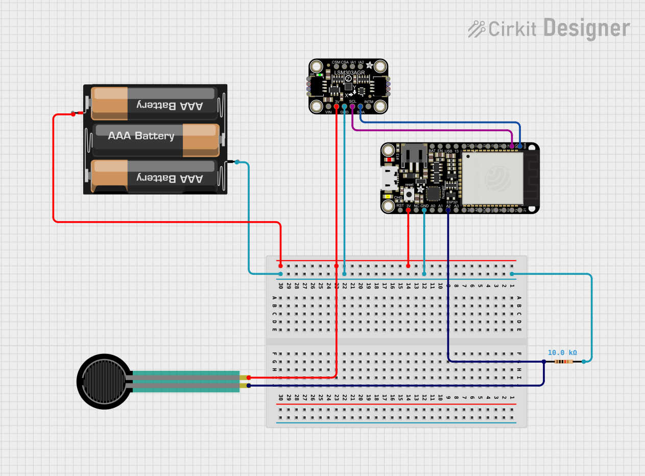
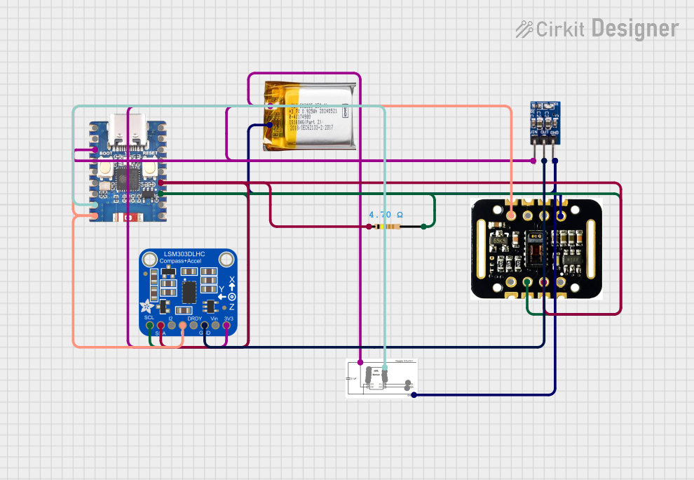

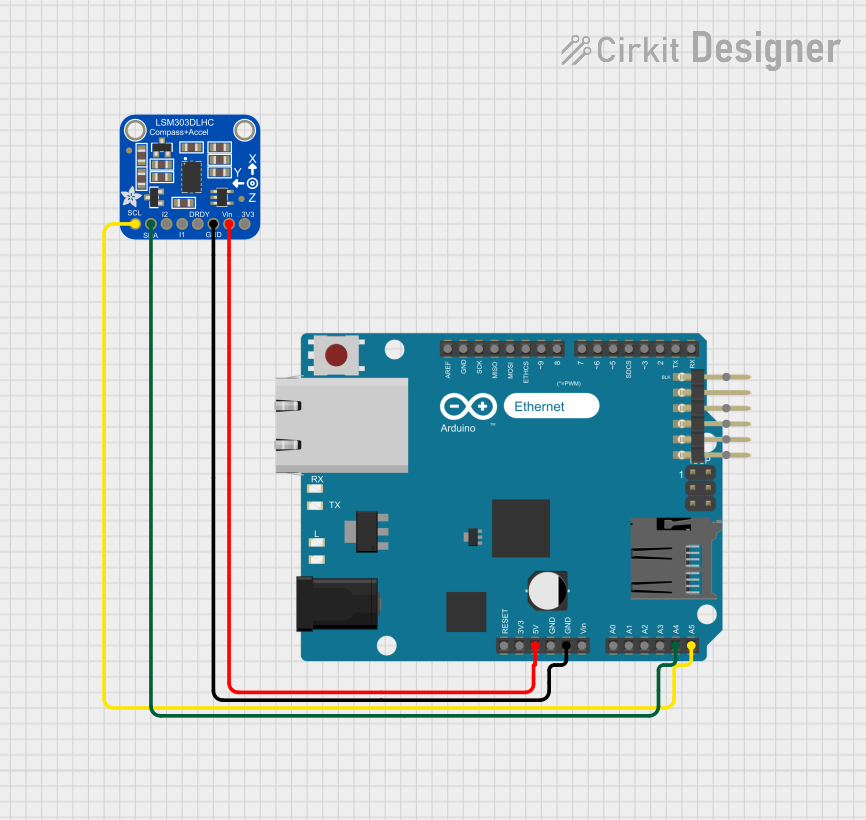
Explore Projects Built with Adafruit LSM6DSO32
Technical Specifications
Key Features
- Accelerometer Ranges: ±2/±4/±8/±16 g
- Gyroscope Ranges: ±125/±250/±500/±1000/±2000 dps (degrees per second)
- Interface: I2C (up to 400 kHz) and SPI (up to 10 MHz)
- Supply Voltage: 1.71 V to 3.6 V
- Operating Temperature: -40°C to +85°C
- Output Data Rates (ODR): up to 6.66 kHz
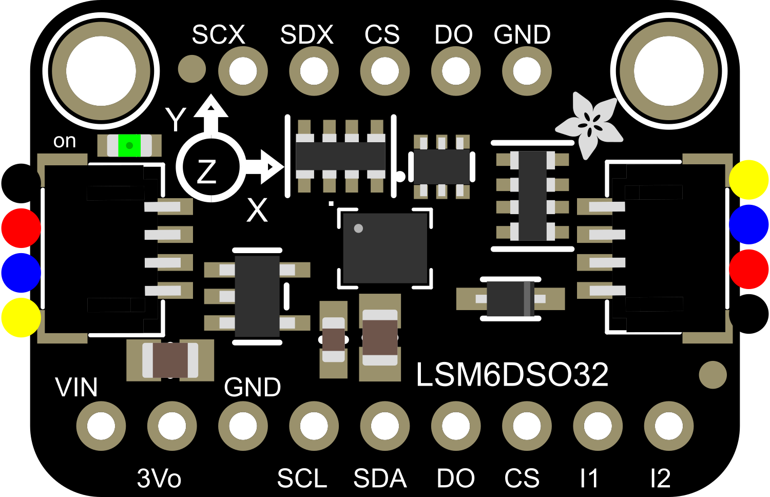
Pin Configuration
| Pin Number | Name | Description |
|---|---|---|
| 1 | SCL | Serial Clock Line for I2C communication |
| 2 | SDA | Serial Data Line for I2C communication |
| 3 | SA0 | I2C Address selection pin |
| 4 | CS | Chip Select for SPI communication |
| 5 | SDO | Serial Data Out for SPI communication |
| 6 | SDI | Serial Data In for SPI communication |
| 7 | GND | Ground reference for the module |
| 8 | VIN | Supply voltage input |
Usage Instructions
Integration into a Circuit
- Power Supply: Connect the VIN pin to a 1.71 V to 3.6 V power source and GND to the ground.
- I2C Communication: Connect SCL to the SCL pin and SDA to the SDA pin of your microcontroller. If required, use pull-up resistors on both lines.
- SPI Communication: Connect CS to a digital pin for chip select, SDO to MISO, SDI to MOSI, and SCL to SCK on your microcontroller.
- Address Selection: The SA0 pin can be used to modify the I2C address if multiple devices are on the same I2C bus.
Best Practices
- Ensure that the power supply is within the specified voltage range to prevent damage.
- Use decoupling capacitors close to the sensor's power supply pin to minimize power supply noise.
- When using I2C, ensure that the bus is not overloaded with too many devices, which can degrade performance.
- For SPI communication, ensure that the CS pin is driven high to low before and after communication to enable and disable the device correctly.
Example Code for Arduino UNO
#include <Wire.h>
#include <Adafruit_LSM6DSO32.h>

Adafruit_LSM6DSO32 lsm6dso32;

void setup() {
  Serial.begin(115200);
  while (!Serial) {
    delay(10); // wait for serial monitor to open
  }

  if (!lsm6dso32.begin_I2C()) {
    Serial.println("Failed to find LSM6DSO32 chip");
    while (1) {
      delay(10);
    }
  }
  Serial.println("LSM6DSO32 Found!");
}

void loop() {
  lsm6dso32.read(); // read data
  Serial.print("Accel X: "); Serial.println(lsm6dso32.acceleration.x);
  Serial.print("Accel Y: "); Serial.println(lsm6dso32.acceleration.y);
  Serial.print("Accel Z: "); Serial.println(lsm6dso32.acceleration.z);

  Serial.print("Gyro X: "); Serial.println(lsm6dso32.gyro.x);
  Serial.print("Gyro Y: "); Serial.println(lsm6dso32.gyro.y);
  Serial.print("Gyro Z: "); Serial.println(lsm6dso32.gyro.z);

  delay(100);
}
This example initializes the LSM6DSO32 over I2C and continuously reads the accelerometer and gyroscope values, printing them to the Serial Monitor.
Troubleshooting and FAQs
Common Issues
- Sensor Not Detected: Ensure that the wiring is correct and that the correct voltage is applied. Check for proper soldering and connections.
- Noisy Data: Ensure that the sensor is not placed near strong electromagnetic fields and that decoupling capacitors are used.
FAQs
Q: Can the LSM6DSO32 be used with a 5V microcontroller? A: Yes, but ensure that the logic levels are shifted to be compatible with the sensor's voltage range.
Q: How can I change the I2C address? A: The I2C address can be changed by connecting the SA0 pin to either ground or VIN.
Q: What is the default I2C address? A: The default I2C address is 0x6B (when SA0 is connected to ground).
Q: How do I calibrate the sensor? A: Calibration involves storing the offset values when the sensor is at rest and then subtracting these values from the readings during operation.
For further assistance, consult the Adafruit LSM6DSO32 datasheet and the Adafruit support forums.