How to Use Thermostat: Examples, Pinouts, and Specs
Introduction
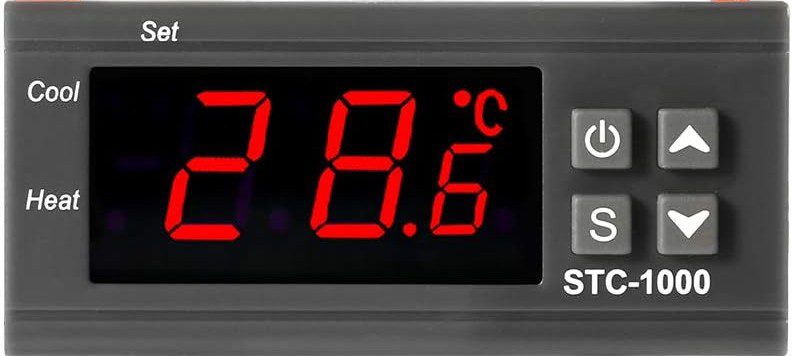
The STC-1000 is a versatile, generic thermostat designed to regulate temperature by controlling heating and cooling systems. It maintains a desired temperature setpoint by switching connected devices on or off based on the measured temperature. This device is widely used in applications such as home brewing, aquariums, refrigeration systems, and greenhouse temperature control.
Explore Projects Built with Thermostat
Explore Projects Built with Thermostat
Common Applications and Use Cases
- Home brewing for precise fermentation temperature control
- Aquariums to maintain optimal water temperature
- Refrigeration systems for food storage
- Greenhouses to regulate environmental conditions
- Incubators for hatching eggs
Technical Specifications
The STC-1000 thermostat is a compact and reliable device with the following key specifications:
| Parameter | Value |
|---|---|
| Operating Voltage | AC 110V-220V |
| Temperature Range | -50°C to 99°C (-58°F to 210°F) |
| Temperature Accuracy | ±1°C |
| Sensor Type | NTC (10kΩ) Thermistor |
| Relay Output (Heating) | 10A at 220V AC |
| Relay Output (Cooling) | 10A at 220V AC |
| Power Consumption | ≤3W |
| Dimensions | 75mm x 34.5mm x 85mm |
| Operating Temperature | -10°C to 60°C |
| Storage Temperature | -20°C to 75°C |
Pin Configuration and Descriptions
The STC-1000 has a simple terminal block for wiring. Below is the pin configuration:
| Pin Number | Label | Description |
|---|---|---|
| 1 | Power (L) | Live wire input for AC power |
| 2 | Power (N) | Neutral wire input for AC power |
| 3 | Cooling (COM) | Common terminal for cooling relay |
| 4 | Cooling (NO) | Normally open terminal for cooling relay |
| 5 | Heating (COM) | Common terminal for heating relay |
| 6 | Heating (NO) | Normally open terminal for heating relay |
| 7 | Sensor Input | Connects to the NTC temperature sensor (one wire) |
| 8 | Sensor Input | Connects to the NTC temperature sensor (other wire) |
Usage Instructions
How to Use the STC-1000 in a Circuit
- Power Connection: Connect the live (L) and neutral (N) wires of the AC power supply to pins 1 and 2, respectively.
- Sensor Connection: Attach the NTC temperature sensor to pins 7 and 8. Ensure the sensor is placed in the environment where temperature regulation is required.
- Load Connection:
- For cooling devices (e.g., fans or refrigeration units), connect the device to pins 3 (COM) and 4 (NO).
- For heating devices (e.g., heaters or heat lamps), connect the device to pins 5 (COM) and 6 (NO).
- Set Temperature: Use the front panel buttons to set the desired temperature and configure the heating/cooling modes.
Important Considerations and Best Practices
- Ensure the total current of connected devices does not exceed the relay's 10A rating.
- Place the NTC sensor in a location that accurately represents the environment's temperature.
- Avoid exposing the device to moisture or extreme conditions beyond its operating range.
- Use proper insulation and secure connections to prevent electrical hazards.
Example: Connecting to an Arduino UNO
While the STC-1000 is a standalone device, it can be integrated with an Arduino UNO for advanced monitoring or control. Below is an example code snippet to read the temperature from the NTC sensor (if directly connected to the Arduino):
// Example code to read temperature from an NTC sensor using Arduino UNO
// Note: This assumes the NTC sensor is connected to analog pin A0.

const int sensorPin = A0; // Analog pin connected to the NTC sensor
const float seriesResistor = 10000.0; // 10kΩ resistor in series with the sensor
const float nominalResistance = 10000.0; // Resistance of the NTC at 25°C
const float nominalTemperature = 25.0; // Nominal temperature in Celsius
const float betaCoefficient = 3950.0; // Beta coefficient of the NTC
const float supplyVoltage = 5.0; // Arduino supply voltage

void setup() {
  Serial.begin(9600); // Initialize serial communication
}

void loop() {
  int sensorValue = analogRead(sensorPin); // Read the analog value
  float voltage = (sensorValue / 1023.0) * supplyVoltage; // Convert to voltage
  float resistance = (supplyVoltage / voltage - 1) * seriesResistor; // Calculate resistance

  // Calculate temperature using the Steinhart-Hart equation
  float steinhart;
  steinhart = resistance / nominalResistance; // (R/Ro)
  steinhart = log(steinhart); // ln(R/Ro)
  steinhart /= betaCoefficient; // 1/B * ln(R/Ro)
  steinhart += 1.0 / (nominalTemperature + 273.15); // + (1/To)
  steinhart = 1.0 / steinhart; // Invert
  steinhart -= 273.15; // Convert to Celsius

  Serial.print("Temperature: ");
  Serial.print(steinhart);
  Serial.println(" °C");

  delay(1000); // Wait 1 second before the next reading
}
Troubleshooting and FAQs
Common Issues and Solutions
Device Does Not Power On:
- Ensure the live (L) and neutral (N) wires are correctly connected to pins 1 and 2.
- Verify the power supply voltage matches the device's operating voltage (110V-220V AC).
Incorrect Temperature Reading:
- Check the NTC sensor connection to pins 7 and 8.
- Ensure the sensor is not damaged or placed in an inappropriate location.
Heating or Cooling Device Does Not Activate:
- Verify the connected device's wiring to the appropriate relay terminals (COM and NO).
- Ensure the device's current does not exceed the relay's 10A rating.
- Check the set temperature and hysteresis settings on the STC-1000.
Relay Clicking Noise:
- This may occur if the hysteresis value is too small. Increase the hysteresis setting to reduce frequent switching.
FAQs
Q: Can the STC-1000 be used with DC-powered devices?
A: No, the STC-1000 is designed for AC-powered devices only. For DC devices, use a compatible DC thermostat.
Q: How do I reset the STC-1000 to factory settings?
A: Press and hold the "SET" button for several seconds until the display resets. Refer to the user manual for detailed instructions.
Q: Can I extend the NTC sensor cable?
A: Yes, but ensure the extension wire is of good quality and does not introduce significant resistance, which could affect temperature readings.
Q: What is the hysteresis setting?
A: Hysteresis defines the temperature range around the setpoint to prevent frequent switching of the relays. For example, if the setpoint is 25°C and hysteresis is 2°C, the relay will activate at 23°C and deactivate at 27°C.