How to Use esp8266: Examples, Pinouts, and Specs
Introduction
The ESP8266 is a highly integrated Wi-Fi module designed for the needs of a new connected world. It offers a complete and self-contained Wi-Fi networking solution, allowing it to either host the application or offload all Wi-Fi networking functions from another application processor. Common applications of the ESP8266 module include smart devices, home automation, wireless sensors, and IoT applications.
Explore Projects Built with esp8266


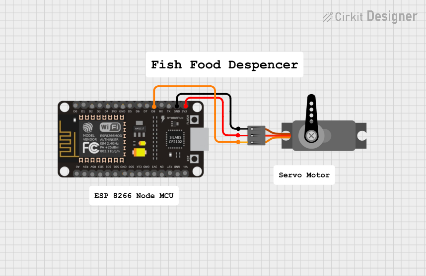
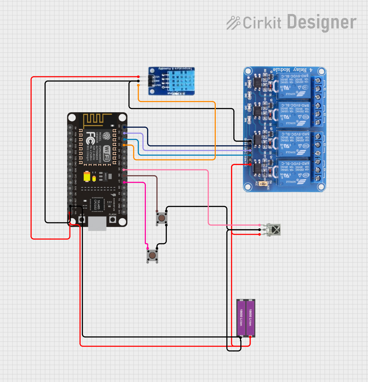
Explore Projects Built with esp8266
Technical Specifications
Key Technical Details
- Wi-Fi Protocols: IEEE 802.11 b/g/n
- Frequency Range: 2.4 GHz - 2.5 GHz (2400M - 2483.5M)
- Operating Voltage: 3.0 - 3.6V (3.3V recommended)
- Operating Current: Average value: 80 mA
- Peak Current: Up to 300 mA
- Integrated TCP/IP protocol stack
- Flash Memory: Typically 512KB to 4MB (depending on the module version)
- Operating Temperature: -40°C to 125°C
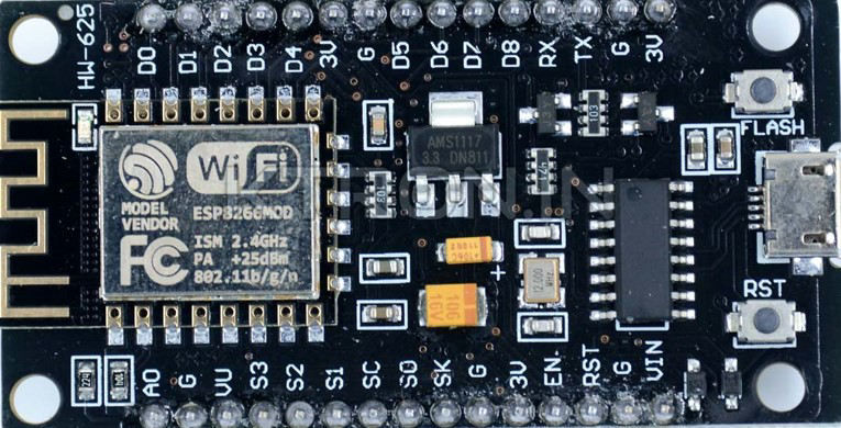
Pin Configuration and Descriptions
| Pin Number | Name | Description |
|---|---|---|
| 1 | GND | Ground |
| 2 | GPIO2 | General Purpose Input/Output 2 |
| 3 | GPIO0 | General Purpose Input/Output 0 |
| 4 | RX | UART Receive Pin |
| 5 | TX | UART Transmit Pin |
| 6 | CH_PD | Chip Power-Down Pin |
| 7 | RST | Reset Pin |
| 8 | VCC | Power Supply (3.3V) |
Usage Instructions
Connecting the ESP8266 to a Circuit
- Power Supply: Connect the VCC pin to a 3.3V power source and the GND pin to ground.
- UART Communication: Connect the RX and TX pins to the corresponding TX and RX pins of your microcontroller or USB-to-serial converter.
- GPIO Usage: GPIO0 and GPIO2 can be used for digital input/output.
- Enabling the Module: The CH_PD pin must be connected to VCC to enable the module.
- Resetting the Module: The RST pin can be connected to a push-button to reset the module manually.
Important Considerations and Best Practices
- Power Supply: Do not exceed the recommended voltage as it can damage the module.
- Antenna: Ensure that the antenna area is clear of metal components to avoid interference.
- Programming: The module can be programmed using the Arduino IDE or other development environments that support the ESP8266.
- Firmware: Update to the latest firmware for improved stability and features.
Example Code for Arduino UNO
#include <ESP8266WiFi.h>

const char* ssid = "yourSSID"; // Replace with your network SSID
const char* password = "yourPASSWORD"; // Replace with your network password

void setup() {
  Serial.begin(115200);
  WiFi.begin(ssid, password);

  while (WiFi.status() != WL_CONNECTED) {
    delay(500);
    Serial.print(".");
  }

  Serial.println("");
  Serial.println("WiFi connected");
}

void loop() {
  // Your code here
}
Troubleshooting and FAQs
Common Issues
- Module Does Not Power On: Ensure that the power supply is correctly connected and within the specified voltage range.
- Cannot Connect to Wi-Fi: Check the SSID and password, and ensure the Wi-Fi network is within range.
- Serial Communication Failure: Verify that the RX and TX connections are correct and the baud rate matches the configuration.
Solutions and Tips for Troubleshooting
- Power Issues: Use a stable 3.3V power supply capable of delivering sufficient current.
- Firmware Flashing: If the module is unresponsive, it may require re-flashing the firmware.
- Connection Stability: For better stability, use an external antenna if your module version supports it.
FAQs
Q: Can the ESP8266 be used with 5V logic? A: No, it is a 3.3V device. Use a logic level converter for 5V systems.
Q: How do I program the ESP8266? A: You can program it using the Arduino IDE with the appropriate board manager installed.
Q: What is the maximum range of the Wi-Fi connection? A: The range depends on the environment but is typically around 100 meters without obstacles.
Q: Can the ESP8266 act as a Wi-Fi access point? A: Yes, the ESP8266 can be configured as an access point or as a Wi-Fi client.
Note: This documentation is for informational purposes only. The manufacturer's datasheet should be consulted for complete technical details and safety information.