How to Use Seeed Studio XIAO nRF52840 Sense Plus: Examples, Pinouts, and Specs
Introduction
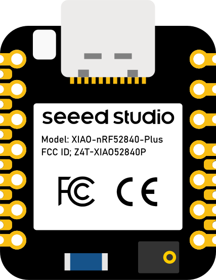
The Seeed Studio XIAO nRF52840 Sense Plus is a compact and powerful microcontroller board based on the Nordic nRF52840 chip. It is designed for IoT applications, wearable devices, and other projects requiring low power consumption, wireless connectivity, and sensor integration. This board features built-in Bluetooth Low Energy (BLE) and NFC capabilities, along with onboard sensors for motion, environmental, and audio data collection. Its small form factor makes it ideal for space-constrained applications.
Explore Projects Built with Seeed Studio XIAO nRF52840 Sense Plus
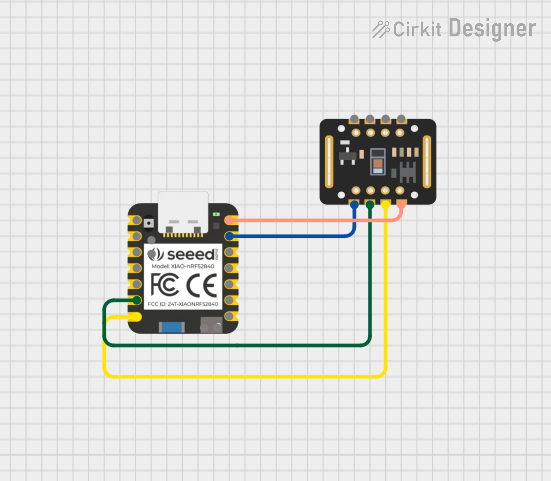
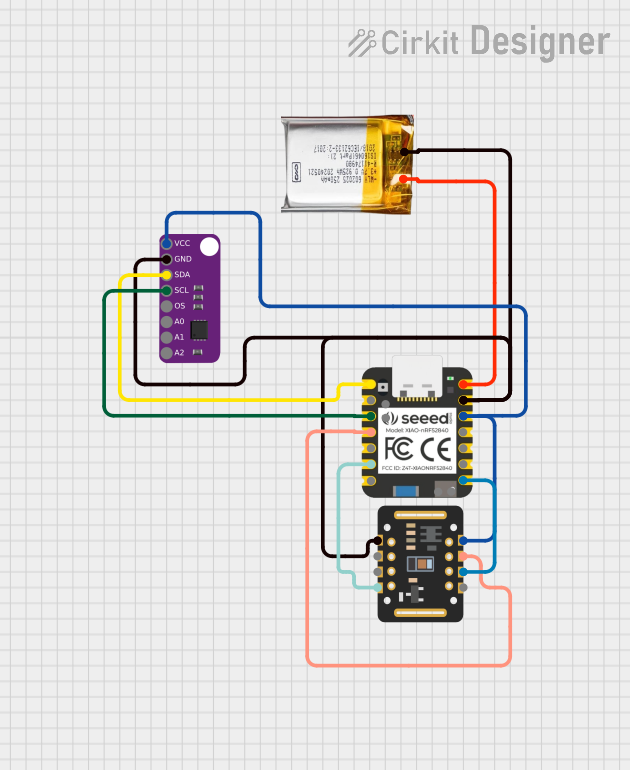
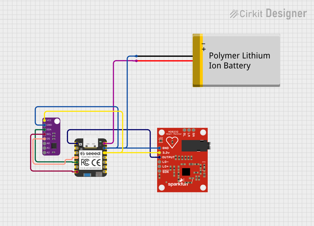

Explore Projects Built with Seeed Studio XIAO nRF52840 Sense Plus
Common Applications and Use Cases
- IoT devices and smart home systems
- Wearable technology (e.g., fitness trackers, health monitors)
- Environmental monitoring (e.g., temperature, humidity, air quality)
- Motion tracking and gesture recognition
- Audio-based applications (e.g., voice recognition, sound detection)
- Prototyping and development of BLE/NFC-enabled devices
Technical Specifications
Key Technical Details
| Specification | Value |
|---|---|
| Microcontroller | Nordic nRF52840 (ARM Cortex-M4F @ 64 MHz) |
| Flash Memory | 1 MB |
| RAM | 256 KB |
| Wireless Connectivity | Bluetooth 5.0 (BLE), NFC |
| Onboard Sensors | IMU (6-axis), PDM Microphone, Temperature |
| Operating Voltage | 3.3V |
| Input Voltage Range | 3.3V - 5V |
| Power Consumption | Ultra-low power |
| Dimensions | 21 x 17.5 mm |
Pin Configuration and Descriptions
| Pin Name | Type | Description |
|---|---|---|
| 3V3 | Power | 3.3V output pin |
| GND | Power | Ground |
| D0-D7 | Digital I/O | General-purpose digital I/O pins |
| A0-A3 | Analog I/O | Analog input/output pins |
| SDA | I2C Data | I2C data line |
| SCL | I2C Clock | I2C clock line |
| RX | UART RX | UART receive pin |
| TX | UART TX | UART transmit pin |
| NFC1, NFC2 | NFC | Near Field Communication pins |
| SWDIO | Debug | SWD data line for debugging |
| SWCLK | Debug | SWD clock line for debugging |
Usage Instructions
How to Use the Component in a Circuit
Powering the Board:
- Connect the board to a 3.3V or 5V power source via the 3V3 pin or USB-C port.
- Ensure the power supply is stable to avoid damaging the board.
Connecting Sensors and Peripherals:
- Use the digital (D0-D7) and analog (A0-A3) pins to interface with external components.
- For I2C devices, connect to the SDA and SCL pins. Ensure proper pull-up resistors are used if required.
Programming the Board:
- The board can be programmed using the Arduino IDE or other compatible environments.
- Install the necessary board support package (BSP) for the Seeed Studio XIAO nRF52840 Sense Plus.
Wireless Communication:
- Use the BLE functionality for wireless data transfer.
- NFC pins can be used for short-range communication or pairing.
Important Considerations and Best Practices
- Voltage Levels: Ensure all connected peripherals operate at 3.3V logic levels to avoid damage.
- Heat Management: Avoid placing the board in environments with excessive heat to maintain performance.
- Firmware Updates: Regularly update the firmware to access the latest features and bug fixes.
- Debugging: Use the SWDIO and SWCLK pins for debugging and troubleshooting.
Example Code for Arduino IDE
The following example demonstrates how to read data from the onboard IMU sensor and send it via BLE:
#include <Wire.h>
#include <Adafruit_Sensor.h>
#include <Adafruit_LSM6DS33.h>
#include <bluefruit.h>

// Create an instance of the IMU sensor
Adafruit_LSM6DS33 imu;

// BLE service and characteristic
BLEService motionService = BLEService(0x180D); // Custom service UUID
BLECharacteristic motionDataChar = BLECharacteristic(0x2A37); // Custom char UUID

void setup() {
  // Initialize serial communication
  Serial.begin(115200);
  while (!Serial);

  // Initialize the IMU sensor
  if (!imu.begin_I2C()) {
    Serial.println("Failed to initialize IMU sensor!");
    while (1);
  }
  Serial.println("IMU sensor initialized.");

  // Initialize BLE
  Bluefruit.begin();
  Bluefruit.setName("XIAO nRF52840");
  motionService.begin();
  motionDataChar.setProperties(CHR_PROPS_NOTIFY);
  motionDataChar.begin();
  Bluefruit.Advertising.start();
  Serial.println("BLE initialized and advertising.");
}

void loop() {
  sensors_event_t accel, gyro, temp;
  imu.getEvent(&accel, &gyro, &temp);

  // Print accelerometer data to serial monitor
  Serial.print("Accel X: "); Serial.print(accel.acceleration.x);
  Serial.print(", Y: "); Serial.print(accel.acceleration.y);
  Serial.print(", Z: "); Serial.println(accel.acceleration.z);

  // Send accelerometer data via BLE
  char motionData[20];
  snprintf(motionData, sizeof(motionData), "X:%.2f,Y:%.2f,Z:%.2f",
           accel.acceleration.x, accel.acceleration.y, accel.acceleration.z);
  motionDataChar.notify(motionData);

  delay(100); // Delay for stability
}
Troubleshooting and FAQs
Common Issues and Solutions
Board Not Detected by Computer:
- Ensure the USB-C cable is data-capable (not just for charging).
- Check if the correct board and port are selected in the Arduino IDE.
BLE Connection Fails:
- Verify that the BLE device is within range.
- Ensure no other devices are interfering with the BLE signal.
- Restart the board and retry pairing.
IMU Sensor Not Responding:
- Check the I2C connections and ensure no loose wires.
- Verify that the correct I2C address is being used in the code.
Power Issues:
- Ensure the power supply provides sufficient current (at least 500mA).
- Avoid using long or thin wires for power connections to minimize voltage drops.
FAQs
Q: Can I use this board with CircuitPython?
A: Yes, the Seeed Studio XIAO nRF52840 Sense Plus supports CircuitPython. You can install the CircuitPython firmware and use it for development.
Q: What is the range of the BLE module?
A: The BLE module typically has a range of up to 10-30 meters, depending on environmental factors and obstacles.
Q: How do I reset the board?
A: Press the reset button twice quickly to enter bootloader mode. This allows you to upload new firmware or reset the board.
Q: Can I use this board for battery-powered applications?
A: Yes, the board is designed for low-power applications and can be powered by a Li-Po battery via the 3V3 pin.