How to Use ESP32 DEVKIT V1: Examples, Pinouts, and Specs
Introduction
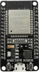
The ESP32 DEVKIT V1, manufactured by Espressif, is a versatile development board built around the powerful ESP32 chip. It features integrated Wi-Fi and Bluetooth capabilities, making it an excellent choice for Internet of Things (IoT) applications, smart devices, and rapid prototyping. With its dual-core processor, low power consumption, and extensive GPIO options, the ESP32 DEVKIT V1 is suitable for a wide range of projects, from home automation to wearable devices.
Explore Projects Built with ESP32 DEVKIT V1


Explore Projects Built with ESP32 DEVKIT V1
Common Applications and Use Cases
- IoT devices and smart home systems
- Wireless sensor networks
- Wearable technology
- Robotics and automation
- Prototyping and educational projects
- Bluetooth Low Energy (BLE) applications
Technical Specifications
The ESP32 DEVKIT V1 is designed to provide robust performance and flexibility. Below are its key technical specifications:
Key Technical Details
- Microcontroller: ESP32-D0WDQ6 chip
- Processor: Dual-core Xtensa® 32-bit LX6 CPU, up to 240 MHz
- Wireless Connectivity: Wi-Fi 802.11 b/g/n and Bluetooth 4.2 (Classic + BLE)
- Flash Memory: 4 MB (varies by model)
- Operating Voltage: 3.3V
- Input Voltage (via USB): 5V
- GPIO Pins: 30 (varies slightly by board version)
- ADC Channels: 18 (12-bit resolution)
- DAC Channels: 2 (8-bit resolution)
- PWM Outputs: 16
- I2C, SPI, UART: Supported
- Power Consumption: Ultra-low power consumption in deep sleep mode (~10 µA)
- Dimensions: 54 mm x 27 mm
Pin Configuration and Descriptions
The ESP32 DEVKIT V1 features a 30-pin layout. Below is the pin configuration:
| Pin | Name | Description |
|---|---|---|
| 1 | EN | Enable pin. Pulling this pin low resets the chip. |
| 2 | IO0 | GPIO0. Used for boot mode selection during programming. |
| 3 | IO1 (TX0) | GPIO1. UART0 TX pin. |
| 4 | IO3 (RX0) | GPIO3. UART0 RX pin. |
| 5 | IO4 | GPIO4. General-purpose I/O pin. |
| 6 | IO5 | GPIO5. General-purpose I/O pin. |
| 7 | GND | Ground pin. |
| 8 | VIN | Input voltage (5V) when powering via an external source. |
| 9 | IO12 | GPIO12. Can be used as an ADC or general-purpose pin. |
| 10 | IO13 | GPIO13. Can be used as an ADC or general-purpose pin. |
| 11 | IO14 | GPIO14. Supports PWM, ADC, and general-purpose functions. |
| 12 | IO15 | GPIO15. Supports PWM, ADC, and general-purpose functions. |
| 13 | IO16 | GPIO16. General-purpose I/O pin. |
| 14 | IO17 | GPIO17. General-purpose I/O pin. |
| 15 | IO18 | GPIO18. SPI clock pin (SCK). |
| 16 | IO19 | GPIO19. SPI data pin (MISO). |
| 17 | IO21 | GPIO21. I2C data pin (SDA). |
| 18 | IO22 | GPIO22. I2C clock pin (SCL). |
| 19 | IO23 | GPIO23. SPI data pin (MOSI). |
| 20 | GND | Ground pin. |
| 21 | IO25 | GPIO25. DAC output or general-purpose pin. |
| 22 | IO26 | GPIO26. DAC output or general-purpose pin. |
| 23 | IO27 | GPIO27. General-purpose I/O pin. |
| 24 | IO32 | GPIO32. ADC input or general-purpose pin. |
| 25 | IO33 | GPIO33. ADC input or general-purpose pin. |
| 26 | IO34 | GPIO34. ADC input (input-only pin). |
| 27 | IO35 | GPIO35. ADC input (input-only pin). |
| 28 | 3V3 | 3.3V output pin. |
| 29 | GND | Ground pin. |
| 30 | IO36 | GPIO36. ADC input (input-only pin). |
Usage Instructions
The ESP32 DEVKIT V1 is easy to use and can be programmed using the Arduino IDE or Espressif's ESP-IDF framework. Below are the steps to get started:
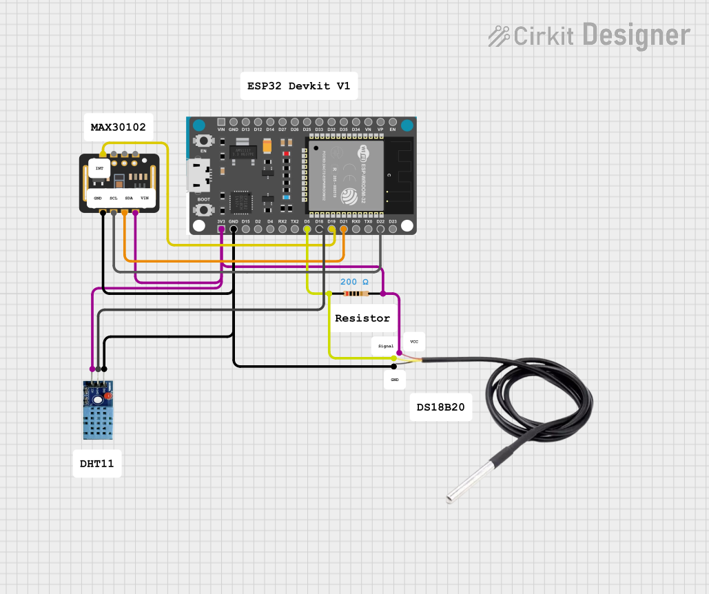
How to Use the Component in a Circuit
Powering the Board:
- Connect the board to your computer via a micro-USB cable. This provides both power and a communication interface for programming.
- Alternatively, supply 5V to the VIN pin or 3.3V to the 3V3 pin for external power.
Programming the Board:
- Install the ESP32 board support package in the Arduino IDE or use the ESP-IDF framework.
- Select the correct board ("ESP32 DEVKIT V1") and port in the IDE.
- Write your code and upload it to the board.
Connecting Peripherals:
- Use the GPIO pins to connect sensors, actuators, or other peripherals.
- Ensure that the voltage levels of connected devices are compatible with the ESP32's 3.3V logic.
Important Considerations and Best Practices
- Voltage Levels: The ESP32 operates at 3.3V. Avoid connecting 5V signals directly to its GPIO pins to prevent damage.
- Boot Mode: To enter programming mode, ensure GPIO0 is pulled low during reset.
- Power Supply: Use a stable power source to avoid unexpected resets or performance issues.
- Deep Sleep Mode: Utilize the deep sleep mode for battery-powered applications to conserve energy.
Example Code for Arduino IDE
Below is an example of how to blink an LED connected to GPIO2:
// Define the GPIO pin for the LED
const int ledPin = 2;

void setup() {
  // Initialize the LED pin as an output
  pinMode(ledPin, OUTPUT);
}

void loop() {
  // Turn the LED on
  digitalWrite(ledPin, HIGH);
  delay(1000); // Wait for 1 second

  // Turn the LED off
  digitalWrite(ledPin, LOW);
  delay(1000); // Wait for 1 second
}
Troubleshooting and FAQs
Common Issues Users Might Face
Board Not Detected in Arduino IDE:
- Ensure the correct USB driver is installed for the ESP32.
- Check that the correct COM port is selected in the IDE.
Upload Fails with "Failed to Connect" Error:
- Hold the "BOOT" button on the board while uploading the code.
- Verify that the correct board and port are selected in the IDE.
Unstable Operation or Random Resets:
- Use a stable power supply with sufficient current (at least 500 mA).
- Check for loose connections or short circuits.
Wi-Fi Connection Issues:
- Ensure the correct SSID and password are used in the code.
- Check for interference or weak signal strength.
Solutions and Tips for Troubleshooting
- Use a multimeter to verify power supply voltages.
- Test the board with a simple sketch (e.g., blinking an LED) to confirm basic functionality.
- Update the ESP32 board package in the Arduino IDE to the latest version.
- Refer to the Espressif documentation for advanced debugging techniques.
By following this documentation, users can effectively utilize the ESP32 DEVKIT V1 for a wide range of applications.