How to Use CAN Transceiver MCP2518FD: Examples, Pinouts, and Specs
Introduction
The MCP2518FD is a high-speed Controller Area Network (CAN) transceiver manufactured by Soldered (Part ID: 333020). It is designed to facilitate communication between microcontrollers and CAN networks, supporting both the classic CAN protocol and the more advanced CAN FD (Flexible Data-rate) protocol. With data rates of up to 1 Mbps for classic CAN and up to 8 Mbps for CAN FD, this transceiver is ideal for applications requiring robust and reliable communication in automotive, industrial, and embedded systems.
Explore Projects Built with CAN Transceiver MCP2518FD

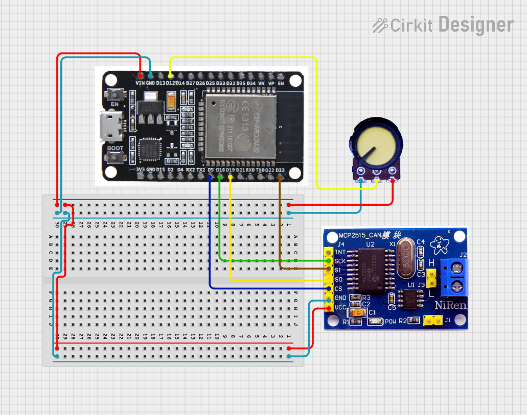
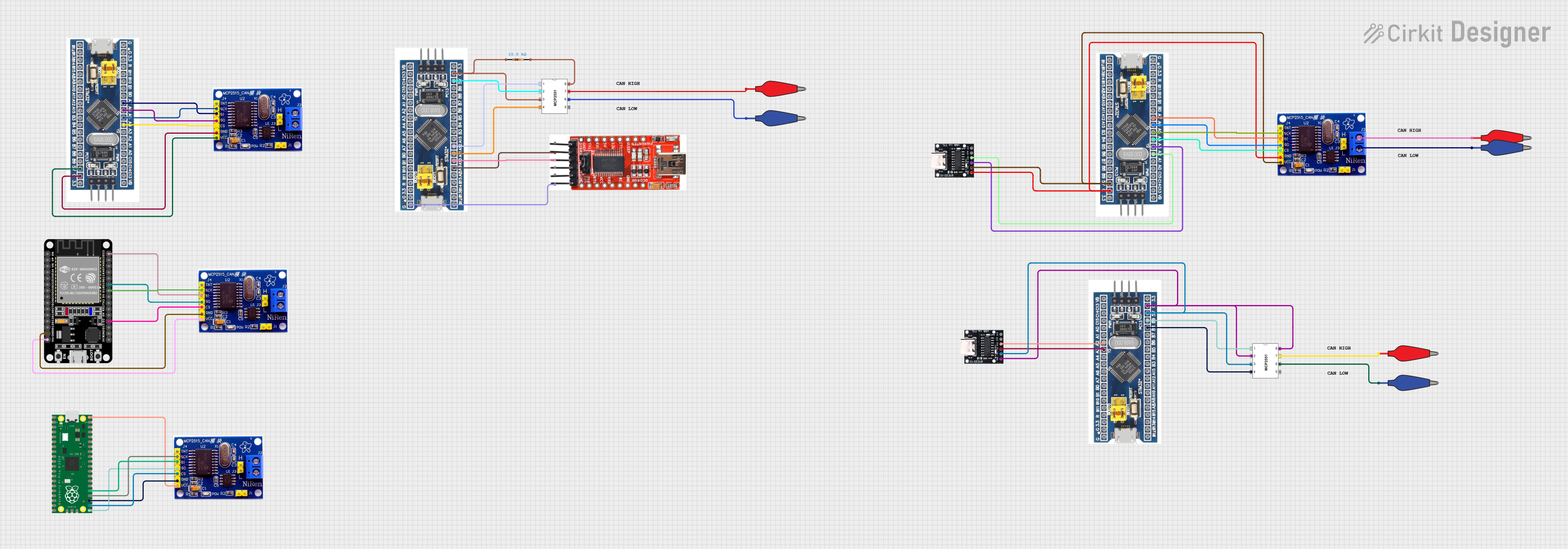
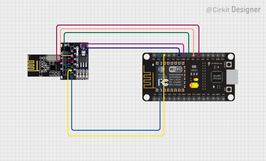
Explore Projects Built with CAN Transceiver MCP2518FD
Common Applications
- Automotive systems (e.g., engine control units, infotainment systems)
- Industrial automation and control
- Robotics and drones
- IoT devices requiring CAN communication
- Medical equipment
Technical Specifications
Key Technical Details
| Parameter | Value |
|---|---|
| Supply Voltage (VDD) | 2.7V to 5.5V |
| CAN Bus Voltage Range | -58V to +58V |
| Data Rate | Up to 1 Mbps (Classic CAN), 8 Mbps (CAN FD) |
| Operating Temperature | -40°C to +125°C |
| Communication Interface | SPI (Serial Peripheral Interface) |
| Package Type | 14-pin SOIC |
| ESD Protection | ±8 kV (Human Body Model) |
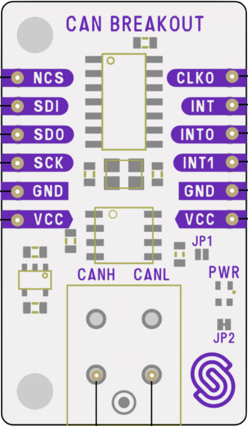
Pin Configuration and Descriptions
The MCP2518FD features a 14-pin configuration. Below is the pinout and description:
| Pin Number | Pin Name | Description |
|---|---|---|
| 1 | VDD | Power supply input (2.7V to 5.5V). |
| 2 | TXD | Transmit data input from the microcontroller. |
| 3 | RXD | Receive data output to the microcontroller. |
| 4 | VSS | Ground connection. |
| 5 | CANH | High-level CAN bus line. |
| 6 | CANL | Low-level CAN bus line. |
| 7 | STBY | Standby mode control input. |
| 8 | VIO | Logic level reference voltage input. |
| 9 | SCK | SPI clock input. |
| 10 | SI | SPI data input. |
| 11 | SO | SPI data output. |
| 12 | CS | SPI chip select input. |
| 13 | INT | Interrupt output to signal events to the microcontroller. |
| 14 | RESET | Active-low reset input to initialize the transceiver. |
Usage Instructions
How to Use the MCP2518FD in a Circuit
- Power Supply: Connect the VDD pin to a regulated power supply (2.7V to 5.5V) and the VSS pin to ground.
- CAN Bus Connection: Connect the CANH and CANL pins to the CAN bus lines. Use appropriate termination resistors (typically 120Ω) at both ends of the CAN bus.
- Microcontroller Interface:
- Connect the SPI pins (SCK, SI, SO, CS) to the corresponding SPI pins on the microcontroller.
- Use the TXD and RXD pins for data transmission and reception.
- Standby Mode: Use the STBY pin to enable or disable standby mode. Pull it low for normal operation.
- Interrupt Handling: Connect the INT pin to a GPIO pin on the microcontroller to handle interrupts.
- Reset: Use the RESET pin to initialize the transceiver during startup or after a fault.
Important Considerations
- Ensure proper decoupling capacitors (e.g., 0.1 µF and 10 µF) are placed near the VDD pin to stabilize the power supply.
- Use twisted-pair cables for the CANH and CANL lines to minimize electromagnetic interference (EMI).
- Verify that the SPI clock frequency is compatible with the MCP2518FD's specifications.
- Always include termination resistors on the CAN bus to prevent signal reflections.
Example Code for Arduino UNO
Below is an example of how to interface the MCP2518FD with an Arduino UNO using the SPI library:
#include <SPI.h>

// Define MCP2518FD SPI pins
const int CS_PIN = 10;  // Chip Select pin
const int INT_PIN = 2;  // Interrupt pin

void setup() {
  // Initialize SPI communication
  SPI.begin();
  pinMode(CS_PIN, OUTPUT);
  pinMode(INT_PIN, INPUT);
  digitalWrite(CS_PIN, HIGH);  // Set CS pin high (inactive)

  Serial.begin(9600);
  Serial.println("Initializing MCP2518FD...");

  // Reset MCP2518FD
  digitalWrite(CS_PIN, LOW);  // Select MCP2518FD
  SPI.transfer(0xC0);         // Send RESET command
  digitalWrite(CS_PIN, HIGH); // Deselect MCP2518FD
  delay(10);                  // Wait for reset to complete

  Serial.println("MCP2518FD initialized.");
}

void loop() {
  // Example: Check for interrupt signal
  if (digitalRead(INT_PIN) == LOW) {
    Serial.println("Interrupt detected!");
    // Handle CAN message or error
  }

  delay(100);
}
Troubleshooting and FAQs
Common Issues and Solutions
No Communication on the CAN Bus
- Cause: Missing or incorrect termination resistors.
- Solution: Ensure 120Ω resistors are placed at both ends of the CAN bus.
SPI Communication Fails
- Cause: Incorrect SPI wiring or clock frequency.
- Solution: Verify the SPI connections and ensure the clock frequency is within the MCP2518FD's supported range.
High Error Rates on the CAN Bus
- Cause: Poor signal integrity or EMI.
- Solution: Use twisted-pair cables for CANH and CANL, and ensure proper grounding.
Device Not Responding After Power-Up
- Cause: Improper initialization or missing reset signal.
- Solution: Ensure the RESET pin is toggled low during startup.
FAQs
Q: Can the MCP2518FD operate with 3.3V logic levels?
A: Yes, the MCP2518FD supports logic levels as low as 2.7V via the VIO pin.
Q: Is the MCP2518FD compatible with the CAN FD protocol?
A: Yes, it supports both classic CAN and CAN FD protocols with data rates up to 8 Mbps for CAN FD.
Q: Do I need external components for ESD protection?
A: The MCP2518FD includes built-in ESD protection (±8 kV), but additional protection may be added for harsh environments.
Q: Can I use the MCP2518FD with a 5V microcontroller?
A: Yes, the MCP2518FD is compatible with 5V systems. Ensure the VIO pin matches the microcontroller's logic level.