How to Use STS35 High Accuracy Digital Temperature Sensor: Examples, Pinouts, and Specs
Introduction
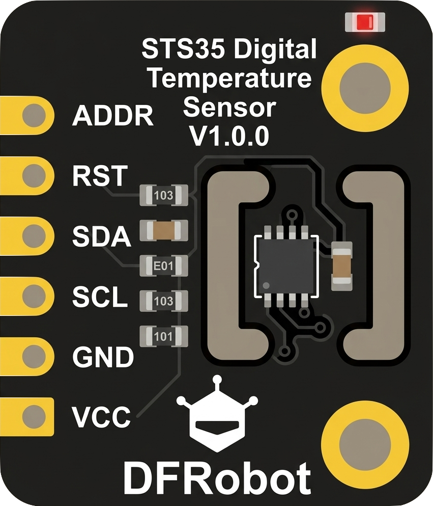
The STS35 is a high-accuracy digital temperature sensor manufactured by DFRobot. It is designed to provide precise temperature readings with a high resolution, making it ideal for applications requiring reliable environmental monitoring and control. The sensor communicates via an I2C interface, ensuring easy integration into a wide range of systems. Its compact size and low power consumption make it suitable for industrial, medical, and consumer electronics applications.
Explore Projects Built with STS35 High Accuracy Digital Temperature Sensor

Explore Projects Built with STS35 High Accuracy Digital Temperature Sensor
Common Applications
- Environmental monitoring systems
- Industrial process control
- HVAC (Heating, Ventilation, and Air Conditioning) systems
- Medical devices
- IoT (Internet of Things) applications
Technical Specifications
The following table outlines the key technical specifications of the STS35 sensor:
| Parameter | Value |
|---|---|
| Supply Voltage (VDD) | 2.4V to 5.5V |
| Current Consumption | 1.7 µA (standby), 550 µA (active) |
| Temperature Range | -40°C to +125°C |
| Temperature Accuracy | ±0.1°C (typical) |
| Communication Interface | I2C (up to 1 MHz) |
| Resolution | 0.01°C |
| Operating Humidity Range | 0% to 100% RH (non-condensing) |
| Package Type | DFN-8 (3.0 mm x 3.0 mm) |
Pin Configuration and Descriptions
The STS35 sensor has 8 pins, as described in the table below:
| Pin Number | Pin Name | Description |
|---|---|---|
| 1 | VDD | Power supply (2.4V to 5.5V) |
| 2 | SDA | I2C data line |
| 3 | GND | Ground |
| 4 | SCL | I2C clock line |
| 5 | ALERT | Programmable alert output (optional use) |
| 6 | NC | Not connected (leave unconnected) |
| 7 | NC | Not connected (leave unconnected) |
| 8 | ADDR | I2C address selection (connect to GND or VDD) |
Usage Instructions
How to Use the STS35 in a Circuit
- Power Supply: Connect the VDD pin to a 2.4V to 5.5V power source and the GND pin to ground.
- I2C Communication: Connect the SDA and SCL pins to the corresponding I2C data and clock lines of your microcontroller. Use pull-up resistors (typically 4.7 kΩ) on both lines.
- I2C Address Selection: Use the ADDR pin to set the I2C address:
- Connect to GND for the default address (0x4A).
- Connect to VDD for an alternate address (0x4B).
- Optional Alert Pin: The ALERT pin can be configured to trigger when the temperature exceeds a user-defined threshold. This pin is optional and can be left unconnected if not used.
Important Considerations
- Ensure the sensor is not exposed to condensation or liquid water, as it is designed for non-condensing environments.
- Avoid placing the sensor near heat sources or in direct sunlight, as this may affect accuracy.
- Use decoupling capacitors (e.g., 0.1 µF) near the VDD pin to stabilize the power supply.
Example Code for Arduino UNO
Below is an example of how to interface the STS35 with an Arduino UNO using the Wire library:
#include <Wire.h>

#define STS35_ADDRESS 0x4A // Default I2C address of the STS35

void setup() {
  Wire.begin(); // Initialize I2C communication
  Serial.begin(9600); // Initialize serial communication for debugging

  // Send a soft reset command to the sensor
  Wire.beginTransmission(STS35_ADDRESS);
  Wire.write(0x30); // Command MSB for soft reset
  Wire.write(0xA2); // Command LSB for soft reset
  Wire.endTransmission();
  delay(10); // Wait for the sensor to reset
}

void loop() {
  float temperature = readTemperature();
  if (!isnan(temperature)) {
    Serial.print("Temperature: ");
    Serial.print(temperature);
    Serial.println(" °C");
  } else {
    Serial.println("Failed to read temperature.");
  }
  delay(1000); // Wait 1 second before the next reading
}

float readTemperature() {
  Wire.beginTransmission(STS35_ADDRESS);
  Wire.write(0x2C); // Command MSB for high repeatability measurement
  Wire.write(0x06); // Command LSB for high repeatability measurement
  Wire.endTransmission();
  delay(50); // Wait for the measurement to complete

  Wire.requestFrom(STS35_ADDRESS, 3); // Request 3 bytes (2 data + 1 checksum)
  if (Wire.available() == 3) {
    uint16_t rawTemp = (Wire.read() << 8) | Wire.read(); // Combine MSB and LSB
    Wire.read(); // Read and discard the checksum
    return -45.0 + 175.0 * (rawTemp / 65535.0); // Convert to Celsius
  }
  return NAN; // Return NaN if the reading fails
}
Notes on the Code
- The example uses the default I2C address (0x4A). If the ADDR pin is connected to VDD, update the
STS35_ADDRESSto 0x4B. - The
readTemperature()function converts the raw sensor data into a temperature value in Celsius.
Troubleshooting and FAQs
Common Issues
No Response from the Sensor
- Ensure the sensor is powered correctly (check VDD and GND connections).
- Verify the I2C address matches the configuration of the ADDR pin.
- Check the pull-up resistors on the SDA and SCL lines.
Incorrect Temperature Readings
- Ensure the sensor is not exposed to heat sources or direct sunlight.
- Verify the I2C communication speed does not exceed 1 MHz.
- Check for proper decoupling capacitors near the VDD pin.
I2C Communication Errors
- Ensure the SDA and SCL lines are not shorted or disconnected.
- Verify the microcontroller supports the I2C clock speed being used.
FAQs
Q: Can the STS35 measure humidity?
A: No, the STS35 is a temperature-only sensor. For temperature and humidity measurements, consider using a sensor like the SHT3x series.
Q: What is the maximum cable length for I2C communication?
A: The maximum cable length depends on the pull-up resistor values and the I2C clock speed. For typical applications, keep the cable length under 1 meter to ensure reliable communication.
Q: Can the sensor operate in a vacuum?
A: The STS35 is not designed for vacuum environments. It is intended for use in standard atmospheric conditions.
Q: How do I calibrate the sensor?
A: The STS35 is factory-calibrated and does not require user calibration.