How to Use ACS 724 Curent Sensor: Examples, Pinouts, and Specs
Introduction
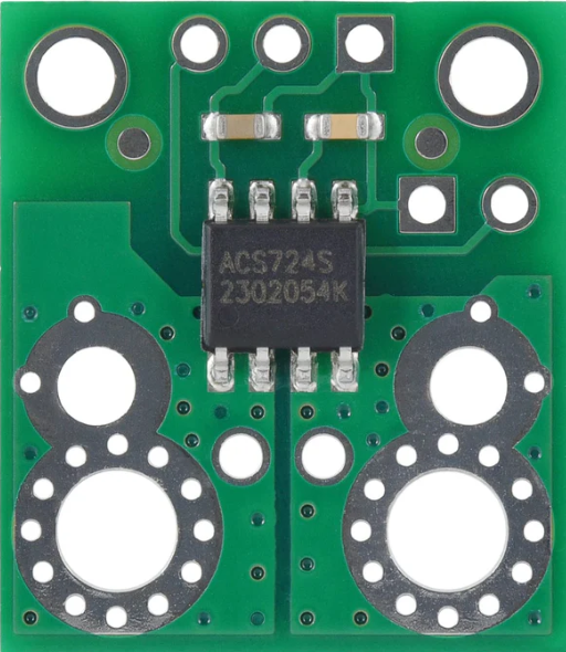
The ACS724 is a Hall-effect current sensor manufactured by Pololu, designed for accurate and isolated current measurements. It is capable of measuring both AC and DC currents, making it suitable for a wide range of applications. The sensor provides a linear analog voltage output proportional to the current being measured, ensuring precise and reliable readings. Its high-voltage isolation capability makes it ideal for use in industrial, automotive, and consumer electronics.
Explore Projects Built with ACS 724 Curent Sensor


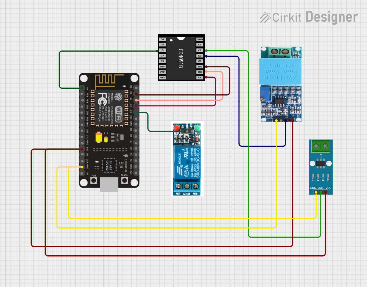

Explore Projects Built with ACS 724 Curent Sensor
Common Applications
- Motor control and monitoring
- Power supply and battery management systems
- Overcurrent protection circuits
- Energy metering and monitoring
- Robotics and automation systems
Technical Specifications
The ACS724 is available in different variants to support various current ranges. Below are the key technical details:
| Parameter | Value |
|---|---|
| Manufacturer | Pololu |
| Part Number | ACS724 |
| Current Sensing Range | ±5 A, ±20 A, or ±50 A (variant-dependent) |
| Supply Voltage (Vcc) | 4.5 V to 5.5 V |
| Output Voltage Range | 0.5 V to 4.5 V |
| Sensitivity | 40 mV/A (±50 A variant) |
| Isolation Voltage | 2.1 kV RMS |
| Operating Temperature Range | -40°C to 150°C |
| Response Time | 5 µs |
Pin Configuration and Descriptions
The ACS724 is typically available in an SOIC-8 package. Below is the pinout and description:
| Pin Number | Pin Name | Description |
|---|---|---|
| 1 | VCC | Power supply input (4.5 V to 5.5 V) |
| 2 | GND | Ground connection |
| 3 | IP+ | Positive current input terminal |
| 4 | IP- | Negative current input terminal |
| 5 | NC | No connection (leave unconnected) |
| 6 | NC | No connection (leave unconnected) |
| 7 | VIOUT | Analog voltage output proportional to sensed current |
| 8 | NC | No connection (leave unconnected) |
Usage Instructions
How to Use the ACS724 in a Circuit
- Power Supply: Connect the VCC pin to a 5 V power supply and the GND pin to the ground of your circuit.
- Current Measurement:
- Pass the current to be measured through the IP+ and IP- terminals. Ensure the current does not exceed the rated range of the specific ACS724 variant.
- The sensor provides an analog voltage output on the VIOUT pin, which is proportional to the current flowing through the IP+ and IP- terminals.
- Output Reading:
- The output voltage at VIOUT is centered around 2.5 V (for 0 A current). A positive current increases the output voltage, while a negative current decreases it.
- Use an ADC (Analog-to-Digital Converter) to read the output voltage and calculate the current using the sensor's sensitivity.
Important Considerations and Best Practices
- Bypass Capacitor: Place a 0.1 µF ceramic capacitor close to the VCC and GND pins to stabilize the power supply.
- Current Path: Ensure the current path through IP+ and IP- is properly connected and isolated from other circuit elements.
- Thermal Management: Avoid exceeding the maximum operating temperature to prevent damage to the sensor.
- Noise Filtering: If the output signal is noisy, consider adding a low-pass filter to the VIOUT pin.
Example: Connecting ACS724 to an Arduino UNO
Below is an example of how to connect the ACS724 to an Arduino UNO and read the current:
Circuit Connections
- Connect the VCC pin of the ACS724 to the 5 V pin of the Arduino.
- Connect the GND pin of the ACS724 to the GND pin of the Arduino.
- Connect the VIOUT pin of the ACS724 to an analog input pin (e.g., A0) on the Arduino.
- Pass the current to be measured through the IP+ and IP- terminals.
Arduino Code
// Define the analog input pin connected to the ACS724 VIOUT pin
const int currentSensorPin = A0;

// Define the sensitivity of the ACS724 (in V/A)
// Example: 40 mV/A for the ±50 A variant
const float sensitivity = 0.04; // Sensitivity in volts per ampere

// Define the zero-current output voltage (2.5 V for ACS724)
const float zeroCurrentVoltage = 2.5;

void setup() {
  Serial.begin(9600); // Initialize serial communication
}

void loop() {
  // Read the analog value from the sensor
  int sensorValue = analogRead(currentSensorPin);

  // Convert the analog value to voltage (5 V reference, 10-bit ADC)
  float sensorVoltage = sensorValue * (5.0 / 1023.0);

  // Calculate the current (in amperes)
  float current = (sensorVoltage - zeroCurrentVoltage) / sensitivity;

  // Print the current to the Serial Monitor
  Serial.print("Current: ");
  Serial.print(current);
  Serial.println(" A");

  delay(500); // Wait for 500 ms before the next reading
}
Troubleshooting and FAQs
Common Issues and Solutions
No Output Voltage on VIOUT
- Cause: Incorrect power supply or loose connections.
- Solution: Verify that the VCC pin is connected to a 5 V power source and the GND pin is properly grounded.
Inaccurate Current Readings
- Cause: Incorrect sensitivity value or noisy signal.
- Solution: Double-check the sensitivity value for your ACS724 variant. Add a low-pass filter to reduce noise.
Output Voltage Stuck at 2.5 V
- Cause: No current flowing through the IP+ and IP- terminals.
- Solution: Ensure the current path is properly connected and that current is flowing through the sensor.
Overheating
- Cause: Exceeding the maximum current rating.
- Solution: Use the correct ACS724 variant for your application and ensure the current does not exceed the rated range.
FAQs
Can the ACS724 measure both AC and DC currents?
- Yes, the ACS724 can measure both AC and DC currents with high accuracy.
What is the maximum current the ACS724 can handle?
- The maximum current depends on the specific variant. For example, the ±50 A variant can handle up to 50 A.
Is the ACS724 output isolated from the current path?
- Yes, the ACS724 provides galvanic isolation between the current path and the output signal.
Can I use the ACS724 with a 3.3 V microcontroller?
- The ACS724 requires a 5 V power supply, but its output can be read by a 3.3 V ADC if the voltage levels are compatible. Use a voltage divider if necessary.
By following this documentation, you can effectively integrate the ACS724 into your projects for accurate current sensing.