How to Use ESP32 - CAM: Examples, Pinouts, and Specs
Introduction
The ESP32-CAM is a small-sized, low-cost development board that integrates an ESP32-S chip and a camera module. It is a versatile board that combines Wi-Fi and Bluetooth connectivity with image processing capabilities, making it ideal for various Internet of Things (IoT) applications. Common use cases include surveillance cameras, facial recognition systems, home automation, and remote monitoring.
Explore Projects Built with ESP32 - CAM


Explore Projects Built with ESP32 - CAM
Technical Specifications
General Features
- Chipset: ESP32-S dual-core processor
- RAM: 520 KB SRAM
- Flash Memory: 4MB
- Wi-Fi: 802.11b/g/n
- Bluetooth: v4.2 BR/EDR and BLE
- Camera Interface: Supports OV2640 and OV7670 cameras
- I/O: GPIO, UART, SPI, I2C
- Operating Voltage: 5V
- Operating Temperature: -20°C to 85°C
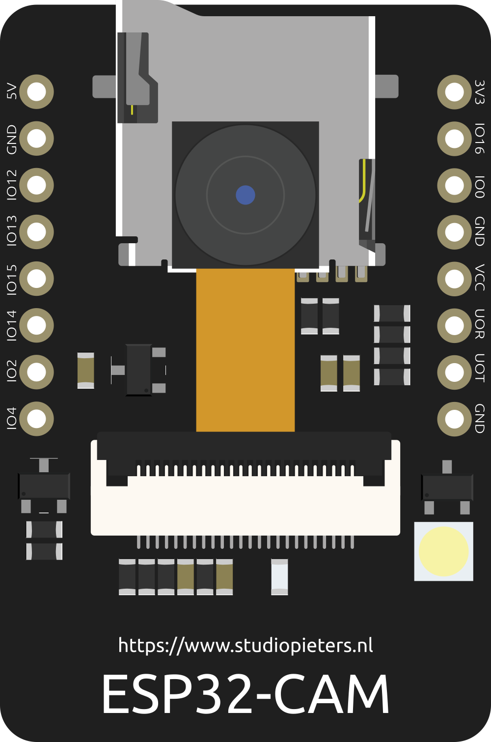
Pin Configuration
| Pin Number | Functionality | Description |
|---|---|---|
| 1 | GND | Ground |
| 2 | 5V | 5V power supply |
| 3 | U0TXD | UART0 Transmit |
| 4 | U0RXD | UART0 Receive |
| 5 | GPIO 3 | General Purpose Input/Output |
| 6 | GPIO 1 | General Purpose Input/Output |
| ... | ... | ... |
| n | GPIO n | General Purpose Input/Output (varies by pin) |
Note: The above table is a simplified representation. Refer to the ESP32-CAM schematic for the complete pinout.
Usage Instructions
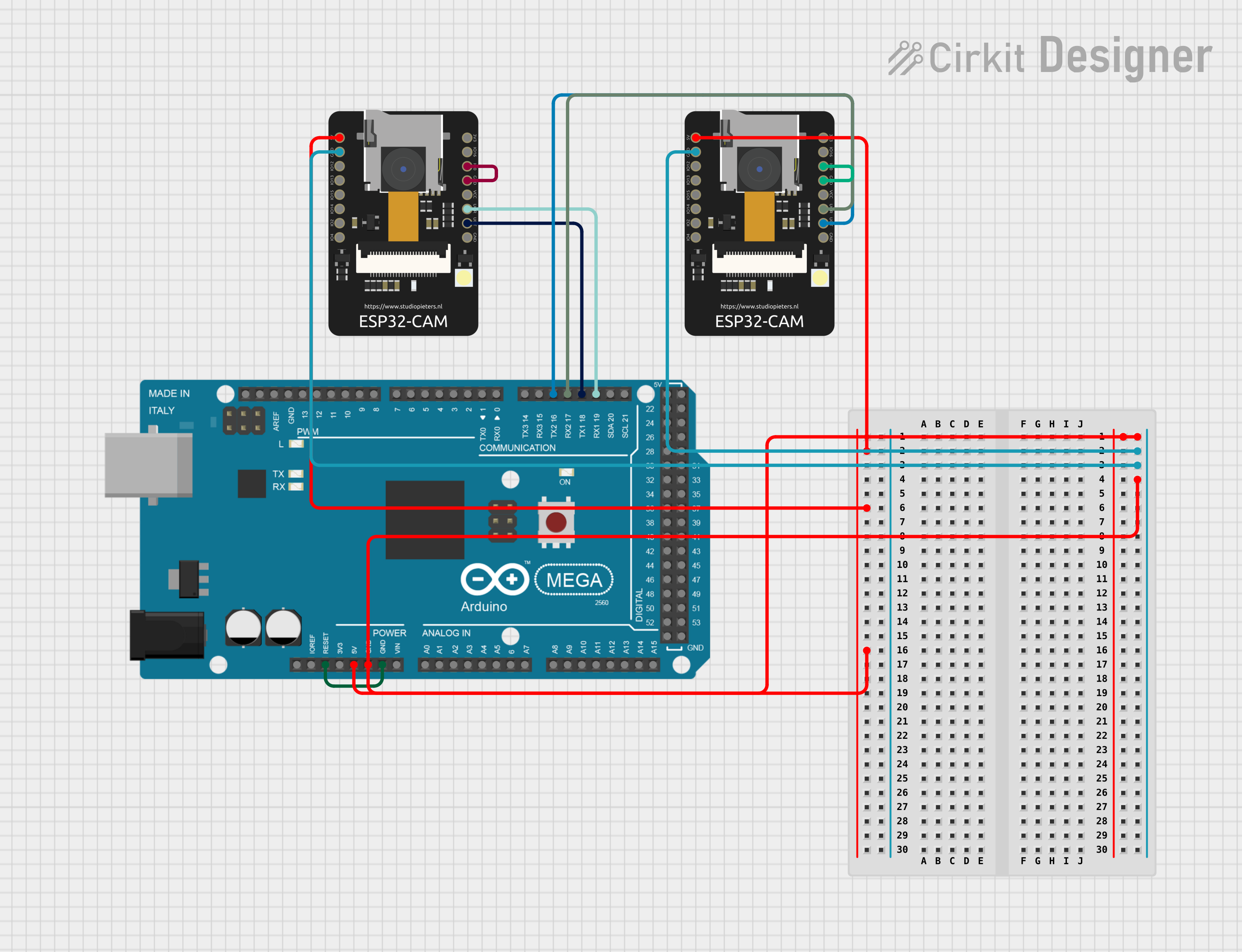
Integrating with a Circuit
- Power Supply: Ensure that the ESP32-CAM is powered with a stable 5V supply. An unstable or incorrect voltage can damage the board.
- Camera Connection: Attach the camera module to the ESP32-CAM board carefully, ensuring proper alignment and connection.
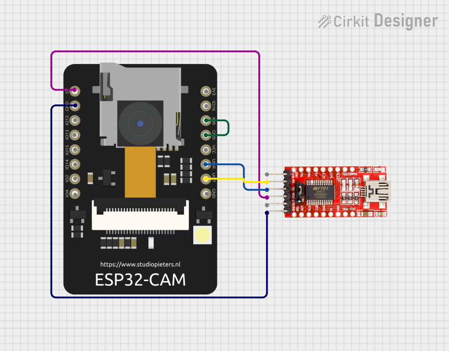
- Programming: The ESP32-CAM does not come with a USB port, so you will need an FTDI programmer to upload code.
- GPIO Access: Use the I/O pins for connecting peripherals, but be aware of the pins used by the camera and other onboard features to avoid conflicts.
Best Practices
- Use a regulated power source to prevent damage.
- Avoid exposing the camera to direct sunlight or high-intensity light to prevent sensor damage.
- Implement proper ESD precautions when handling the board and camera module.
- Ensure firmware is up-to-date for optimal performance and security.
Example Code for Arduino UNO
Below is an example code snippet for capturing an image with the ESP32-CAM and sending it over Wi-Fi. This code assumes that you have the appropriate libraries installed and the board connected to your Arduino IDE.
#include "esp_camera.h"
#include <WiFi.h>

// Replace with your network credentials
const char* ssid = "YOUR_SSID";
const char* password = "YOUR_PASSWORD";

// Camera model pins (AI-THINKER Model)
#define PWDN_GPIO_NUM     32
#define RESET_GPIO_NUM    -1
#define XCLK_GPIO_NUM      0
#define SIOD_GPIO_NUM     26
#define SIOC_GPIO_NUM     27
#define Y9_GPIO_NUM       35
#define Y8_GPIO_NUM       34
#define Y7_GPIO_NUM       39
#define Y6_GPIO_NUM       36
#define Y5_GPIO_NUM       21
#define Y4_GPIO_NUM       19
#define Y3_GPIO_NUM       18
#define Y2_GPIO_NUM        5
#define VSYNC_GPIO_NUM    25
#define HREF_GPIO_NUM     23
#define PCLK_GPIO_NUM     22

void setup() {
  // Serial initialization for debugging
  Serial.begin(115200);

  // Camera configuration
  camera_config_t config;
  config.ledc_channel = LEDC_CHANNEL_0;
  config.ledc_timer = LEDC_TIMER_0;
  config.pin_d0 = Y2_GPIO_NUM;
  config.pin_d1 = Y3_GPIO_NUM;
  config.pin_d2 = Y4_GPIO_NUM;
  config.pin_d3 = Y5_GPIO_NUM;
  config.pin_d4 = Y6_GPIO_NUM;
  config.pin_d5 = Y7_GPIO_NUM;
  config.pin_d6 = Y8_GPIO_NUM;
  config.pin_d7 = Y9_GPIO_NUM;
  config.pin_xclk = XCLK_GPIO_NUM;
  config.pin_pclk = PCLK_GPIO_NUM;
  config.pin_vsync = VSYNC_GPIO_NUM;
  config.pin_href = HREF_GPIO_NUM;
  config.pin_sscb_sda = SIOD_GPIO_NUM;
  config.pin_sscb_scl = SIOC_GPIO_NUM;
  config.pin_pwdn = PWDN_GPIO_NUM;
  config.pin_reset = RESET_GPIO_NUM;
  config.xclk_freq_hz = 20000000;
  config.pixel_format = PIXFORMAT_JPEG;

  // Initialize the Camera
  if (esp_camera_init(&config) != ESP_OK) {
    Serial.println("Camera init failed!");
    return;
  }

  // Connect to Wi-Fi
  WiFi.begin(ssid, password);
  while (WiFi.status() != WL_CONNECTED) {
    delay(500);
    Serial.print(".");
  }
  Serial.println("");
  Serial.println("WiFi connected");
}

void loop() {
  // Capture a photo
  camera_fb_t * fb = esp_camera_fb_get();
  if (!fb) {
    Serial.println("Camera capture failed");
    return;
  }
  // Process captured frame
  // ...
  // Return the frame buffer back to the driver for reuse
  esp_camera_fb_return(fb);
}
Note: This code is for illustration purposes only. You will need to fill in the Wi-Fi credentials and complete the frame processing part.
Troubleshooting and FAQs
Common Issues
- Camera Not Working: Ensure the camera is correctly connected and the pins are properly configured in the code.
- Wi-Fi Connection Issues: Verify that the SSID and password are correct and that the ESP32-CAM is within the range of the Wi-Fi router.
- Board Not Responding: Check the power supply and ensure that the FTDI programmer is correctly connected and configured.
FAQs
Q: Can I use the ESP32-CAM without an FTDI programmer? A: No, you need an FTDI programmer or a similar serial-to-USB converter to program the ESP32-CAM.
Q: How do I update the firmware on the ESP32-CAM? A: Firmware updates can be done through the Arduino IDE or other development platforms by uploading new code to the board.
Q: What is the maximum resolution of the camera? A: The maximum resolution depends on the camera module used. The OV2640 camera module supports up to 2 Megapixels.
For further assistance, consult the ESP32-CAM community forums and the manufacturer's documentation.