Cirkit Designer Logo
Cirkit Designer
Your all-in-one circuit design IDE
Home / 
Component Documentation

How to Use esp32: Examples, Pinouts, and Specs

Image of esp32
Cirkit Designer LogoDesign with esp32 in Cirkit Designer

Introduction

The ESP32 is a low-cost, low-power system on a chip (SoC) developed by Espressif Systems. It features integrated Wi-Fi and Bluetooth capabilities, making it an ideal choice for Internet of Things (IoT) applications, smart devices, and embedded systems. With its dual-core processor, extensive GPIO options, and support for various communication protocols, the ESP32 is a versatile and powerful component for a wide range of projects.

Explore Projects Built with esp32

Use Cirkit Designer to design, explore, and prototype these projects online. Some projects support real-time simulation. Click "Open Project" to start designing instantly!
ESP32-Controlled OLED Display and Servo with DotStar LED Strip and Audio Output
Image of Arena 2: A project utilizing esp32 in a practical application
This circuit features an ESP32 microcontroller driving a variety of components. It controls an OLED display for visual output, a DotStar LED strip for lighting effects, a PAM8403 audio amplifier connected to a speaker for sound output, and a PCA9685 PWM Servo Breakout to manage a servo motor. The ESP32 also interfaces with a piezo speaker for additional sound generation, and the circuit is powered by a 18650 Li-ion battery setup with a TP4056 charging module. The ESP32's embedded code handles the display animation on the OLED.
Cirkit Designer LogoOpen Project in Cirkit Designer
ESP32-Based Sensor Monitoring System with OLED Display and E-Stop
Image of MVP_design: A project utilizing esp32 in a practical application
This circuit features an ESP32 microcontroller that interfaces with a variety of sensors and output devices. It is powered by a Lipo battery through a buck converter, ensuring a stable voltage supply. The ESP32 collects data from a DHT11 temperature and humidity sensor and a vibration sensor, controls a buzzer, and displays information on an OLED screen. An emergency stop (E Stop) is connected for safety purposes, allowing the system to be quickly deactivated.
Cirkit Designer LogoOpen Project in Cirkit Designer
ESP32-Based Environmental Monitoring System with Motion Detection
Image of pro: A project utilizing esp32 in a practical application
This circuit features an ESP32 microcontroller on a baseboard that interfaces with a PIR sensor for motion detection, a DHT22 sensor for measuring temperature and humidity, and a BH1750 sensor for detecting ambient light levels. The ESP32 is configured to communicate with the BH1750 using I2C protocol, with GPIO22 and GPIO21 serving as the SCL and SDA lines, respectively. Power is supplied to the sensors from the ESP32's voltage output pins, and sensor outputs are connected to designated GPIO pins for data acquisition.
Cirkit Designer LogoOpen Project in Cirkit Designer
ESP32-Based Smart Weather Station with Wi-Fi Connectivity
Image of flowchart 3D: A project utilizing esp32 in a practical application
This circuit features an ESP32 microcontroller interfacing with various sensors and modules, including a DHT22 temperature and humidity sensor, an ESP32 CAM for image capture, an I2C LCD screen for display, a load cell with an HX711 interface for weight measurement, and a buzzer for audio alerts. The ESP32 handles data acquisition, processing, and communication with these peripherals to create a multi-functional monitoring and alert system.
Cirkit Designer LogoOpen Project in Cirkit Designer

Explore Projects Built with esp32

Use Cirkit Designer to design, explore, and prototype these projects online. Some projects support real-time simulation. Click "Open Project" to start designing instantly!
Image of Arena 2: A project utilizing esp32 in a practical application
ESP32-Controlled OLED Display and Servo with DotStar LED Strip and Audio Output
This circuit features an ESP32 microcontroller driving a variety of components. It controls an OLED display for visual output, a DotStar LED strip for lighting effects, a PAM8403 audio amplifier connected to a speaker for sound output, and a PCA9685 PWM Servo Breakout to manage a servo motor. The ESP32 also interfaces with a piezo speaker for additional sound generation, and the circuit is powered by a 18650 Li-ion battery setup with a TP4056 charging module. The ESP32's embedded code handles the display animation on the OLED.
Cirkit Designer LogoOpen Project in Cirkit Designer
Image of MVP_design: A project utilizing esp32 in a practical application
ESP32-Based Sensor Monitoring System with OLED Display and E-Stop
This circuit features an ESP32 microcontroller that interfaces with a variety of sensors and output devices. It is powered by a Lipo battery through a buck converter, ensuring a stable voltage supply. The ESP32 collects data from a DHT11 temperature and humidity sensor and a vibration sensor, controls a buzzer, and displays information on an OLED screen. An emergency stop (E Stop) is connected for safety purposes, allowing the system to be quickly deactivated.
Cirkit Designer LogoOpen Project in Cirkit Designer
Image of pro: A project utilizing esp32 in a practical application
ESP32-Based Environmental Monitoring System with Motion Detection
This circuit features an ESP32 microcontroller on a baseboard that interfaces with a PIR sensor for motion detection, a DHT22 sensor for measuring temperature and humidity, and a BH1750 sensor for detecting ambient light levels. The ESP32 is configured to communicate with the BH1750 using I2C protocol, with GPIO22 and GPIO21 serving as the SCL and SDA lines, respectively. Power is supplied to the sensors from the ESP32's voltage output pins, and sensor outputs are connected to designated GPIO pins for data acquisition.
Cirkit Designer LogoOpen Project in Cirkit Designer
Image of flowchart 3D: A project utilizing esp32 in a practical application
ESP32-Based Smart Weather Station with Wi-Fi Connectivity
This circuit features an ESP32 microcontroller interfacing with various sensors and modules, including a DHT22 temperature and humidity sensor, an ESP32 CAM for image capture, an I2C LCD screen for display, a load cell with an HX711 interface for weight measurement, and a buzzer for audio alerts. The ESP32 handles data acquisition, processing, and communication with these peripherals to create a multi-functional monitoring and alert system.
Cirkit Designer LogoOpen Project in Cirkit Designer

Common Applications and Use Cases

  • IoT devices and smart home automation
  • Wireless sensor networks
  • Wearable electronics
  • Robotics and drones
  • Industrial automation
  • Prototyping and educational projects

Technical Specifications

The ESP32 is packed with features that make it suitable for both simple and complex applications. Below are its key technical specifications:

Key Technical Details

  • Processor: Dual-core Xtensa® 32-bit LX6 microprocessor
  • Clock Speed: Up to 240 MHz
  • RAM: 520 KB SRAM
  • Flash Memory: Typically 4 MB (varies by module)
  • Wi-Fi: 802.11 b/g/n (2.4 GHz)
  • Bluetooth: v4.2 BR/EDR and BLE
  • Operating Voltage: 3.0V to 3.6V
  • GPIO Pins: 34 (multiplexed for various functions)
  • ADC Channels: Up to 18 (12-bit resolution)
  • DAC Channels: 2 (8-bit resolution)
  • Communication Protocols: UART, SPI, I2C, I2S, CAN, PWM
  • Power Consumption: Ultra-low power modes available (as low as 5 µA in deep sleep)

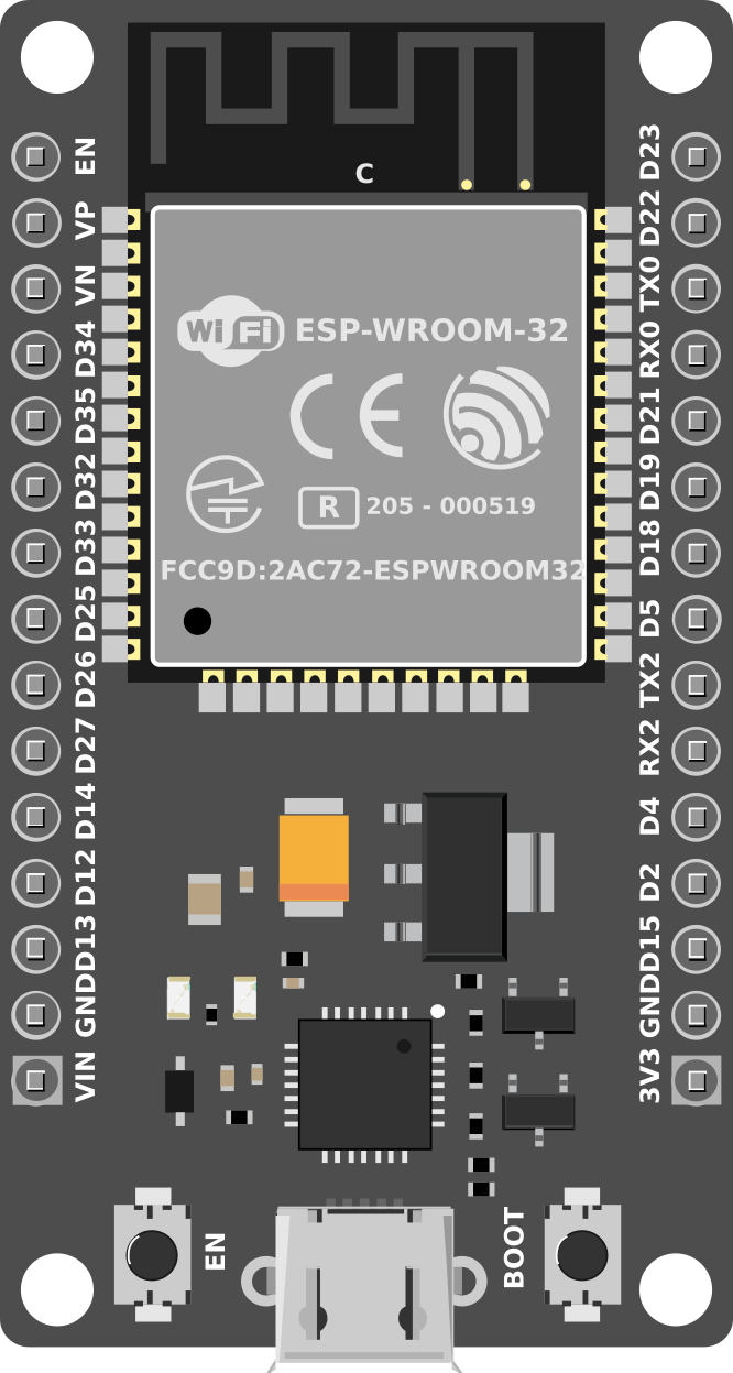
Pin Configuration and Descriptions

The ESP32 has a variety of pins that can be used for different purposes. Below is a table summarizing the most commonly used pins:

Pin Name Function Description
GPIO0 Input/Output, Boot Mode Select Used for boot mode selection during startup.
GPIO2 Input/Output General-purpose I/O pin.
GPIO12 Input/Output, ADC2_CH5 Can be used as an analog input or digital I/O.
GPIO13 Input/Output, ADC2_CH4, Touch4 Supports touch sensing and analog input.
GPIO15 Input/Output, ADC2_CH3, Touch3 Supports touch sensing and analog input.
GPIO16 Input/Output General-purpose I/O pin.
GPIO17 Input/Output General-purpose I/O pin.
EN Enable Active-high pin to enable the chip.
3V3 Power Supply Provides 3.3V output.
GND Ground Ground connection.

Note: The ESP32 has many more pins with specific functions. Refer to the official datasheet for a complete pinout.

Usage Instructions

The ESP32 can be used in a variety of circuits and applications. Below are the steps and best practices for using the ESP32 in your projects.

How to Use the ESP32 in a Circuit

  1. Powering the ESP32:

    • The ESP32 operates at 3.3V. Ensure your power supply provides a stable 3.3V.
    • If using a development board (e.g., ESP32 DevKit), you can power it via USB or a 5V input.
  2. Connecting to Peripherals:

    • Use GPIO pins for digital input/output.
    • For analog input, connect sensors to ADC pins (e.g., GPIO12, GPIO13).
    • For communication, use UART, SPI, or I2C pins as needed.
  3. Programming the ESP32:

    • Install the Arduino IDE or ESP-IDF (Espressif IoT Development Framework).
    • Add the ESP32 board package to the Arduino IDE via the Board Manager.
    • Connect the ESP32 to your computer via USB and select the correct COM port.
  4. Uploading Code:

    • Write your code in the Arduino IDE or ESP-IDF.
    • Compile and upload the code to the ESP32.
    • Monitor the serial output for debugging.

Important Considerations and Best Practices

  • Voltage Levels: The ESP32 operates at 3.3V logic levels. Avoid connecting 5V signals directly to its pins.
  • Boot Mode: Ensure GPIO0 is pulled low during boot to enter programming mode.
  • Power Supply: Use a decoupling capacitor (e.g., 10 µF) near the power pins to stabilize the voltage.
  • Wi-Fi Interference: Keep the antenna area clear of metal objects to ensure good signal strength.

Example Code for Arduino UNO Integration

Below is an example of how to use the ESP32 with the Arduino IDE to blink an LED:

// Example: Blink an LED connected to GPIO2 on the ESP32

// Define the GPIO pin for the LED
#define LED_PIN 2

void setup() {
  pinMode(LED_PIN, OUTPUT); // Set GPIO2 as an output pin
}

void loop() {
  digitalWrite(LED_PIN, HIGH); // Turn the LED on
  delay(1000);                 // Wait for 1 second
  digitalWrite(LED_PIN, LOW);  // Turn the LED off
  delay(1000);                 // Wait for 1 second
}

Note: Ensure the LED is connected to GPIO2 with a current-limiting resistor (e.g., 220Ω).

Troubleshooting and FAQs

Common Issues and Solutions

  1. ESP32 Not Detected by Computer:

    • Ensure the USB cable is functional and supports data transfer.
    • Install the correct USB-to-serial driver (e.g., CP2102 or CH340).
  2. Code Upload Fails:

    • Check that GPIO0 is pulled low during boot.
    • Verify the correct COM port and board are selected in the Arduino IDE.
  3. Wi-Fi Connection Issues:

    • Ensure the Wi-Fi credentials (SSID and password) are correct.
    • Check for interference or weak signal strength.
  4. Random Resets or Instability:

    • Verify the power supply provides sufficient current (at least 500 mA).
    • Add decoupling capacitors near the power pins.

FAQs

Q: Can the ESP32 operate on 5V?
A: No, the ESP32 operates at 3.3V. However, many development boards include a voltage regulator to accept 5V input.

Q: How do I use the ESP32's Bluetooth functionality?
A: The ESP32 supports both Bluetooth Classic and BLE. Use libraries like BluetoothSerial or BLEDevice in the Arduino IDE to implement Bluetooth features.

Q: Can I use the ESP32 for battery-powered projects?
A: Yes, the ESP32 supports ultra-low power modes, making it suitable for battery-powered applications. Use deep sleep mode to conserve power.

Q: What is the maximum range of the ESP32's Wi-Fi?
A: The range depends on the environment but typically extends up to 100 meters in open spaces.

By following this documentation, you can effectively integrate the ESP32 into your projects and troubleshoot common issues. For advanced features, refer to the official Espressif documentation.