Cirkit Designer
Your all-in-one circuit design IDE
Home /
Component Documentation
How to Use SA818s-vhf: Examples, Pinouts, and Specs
Introduction
The SA818s-VHF is a low-cost, high-performance VHF transceiver module that integrates a complete RF transceiver, baseband, and protocol processing. This module is widely used in various wireless communication applications, including amateur radio, walkie-talkies, and other VHF communication devices. Its compact size and robust performance make it an ideal choice for both hobbyists and professionals.
Explore Projects Built with SA818s-vhf
Satellite-Based Timing and Navigation System with SDR and Atomic Clock Synchronization

This circuit appears to be a complex system involving power supply management, GPS and timing synchronization, and data communication. It includes a SI-TEX G1 Satellite Compass for GPS data, an XHTF1021 Atomic Rubidium Clock for precise timing, and Ettus USRP B200 units for software-defined radio communication. Power is supplied through various SMPS units and distributed via terminal blocks and DC jacks. Data communication is facilitated by Beelink MINI S12 N95 computers, RS232 splitters, and a 1000BASE-T Media Converter for network connectivity. RF Directional Couplers are used to interface antennas with the USRP units, and the entire system is likely contained within cases for protection and organization.
Satellite Compass and Network-Integrated GPS Data Processing System

This circuit comprises a satellite compass, a mini PC, two GPS antennas, power supplies, a network switch, media converters, and an atomic rubidium clock. The satellite compass is powered by a triple output DC power supply and interfaces with an RS232 splitter for 1PPS signals. The mini PCs are connected to the USRP B200 devices via USB for data and power, and to media converters via Ethernet, which in turn connect to a network switch using fiber optic links. The antennas are connected to the USRP B200s through RF directional couplers, and the atomic clock provides a 1PPS input to the RS232 splitter.
Raspberry Pi and H743-SLIM V3 Controlled Servo System with GPS and Telemetry
This circuit is designed for a UAV control system, featuring an H743-SLIM V3 flight controller connected to multiple servos for control surfaces, a GPS module for navigation, a telemetry radio for communication, and a digital airspeed sensor for flight data. The system is powered by a LiPo battery and includes a Raspberry Pi for additional processing and control tasks.
Dual-Mode LoRa and GSM Communication Device with ESP32

This circuit features an ESP32 Devkit V1 microcontroller interfaced with an RFM95 LoRa transceiver module for long-range communication and a SIM800L GSM module for cellular connectivity. Two LM2596 step-down modules are used to regulate the 12V battery voltage down to 3.3V required by the ESP32, RFM95, and SIM800L. The ESP32 facilitates data exchange between the RFM95 and SIM800L, enabling the system to send/receive data over both LoRa and GSM networks.
Explore Projects Built with SA818s-vhf
Satellite-Based Timing and Navigation System with SDR and Atomic Clock Synchronization
This circuit appears to be a complex system involving power supply management, GPS and timing synchronization, and data communication. It includes a SI-TEX G1 Satellite Compass for GPS data, an XHTF1021 Atomic Rubidium Clock for precise timing, and Ettus USRP B200 units for software-defined radio communication. Power is supplied through various SMPS units and distributed via terminal blocks and DC jacks. Data communication is facilitated by Beelink MINI S12 N95 computers, RS232 splitters, and a 1000BASE-T Media Converter for network connectivity. RF Directional Couplers are used to interface antennas with the USRP units, and the entire system is likely contained within cases for protection and organization.
Satellite Compass and Network-Integrated GPS Data Processing System
This circuit comprises a satellite compass, a mini PC, two GPS antennas, power supplies, a network switch, media converters, and an atomic rubidium clock. The satellite compass is powered by a triple output DC power supply and interfaces with an RS232 splitter for 1PPS signals. The mini PCs are connected to the USRP B200 devices via USB for data and power, and to media converters via Ethernet, which in turn connect to a network switch using fiber optic links. The antennas are connected to the USRP B200s through RF directional couplers, and the atomic clock provides a 1PPS input to the RS232 splitter.
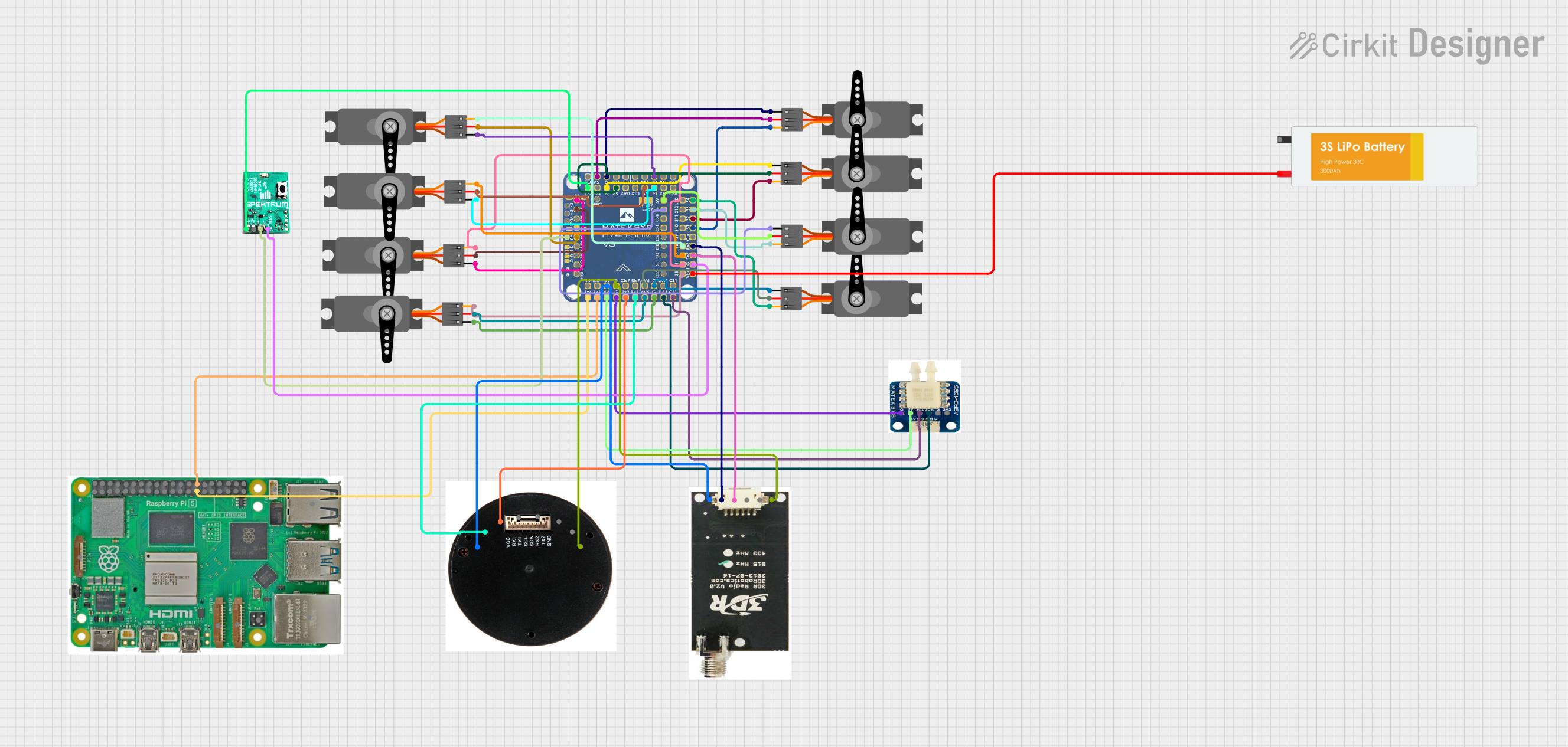
Raspberry Pi and H743-SLIM V3 Controlled Servo System with GPS and Telemetry
This circuit is designed for a UAV control system, featuring an H743-SLIM V3 flight controller connected to multiple servos for control surfaces, a GPS module for navigation, a telemetry radio for communication, and a digital airspeed sensor for flight data. The system is powered by a LiPo battery and includes a Raspberry Pi for additional processing and control tasks.
Dual-Mode LoRa and GSM Communication Device with ESP32
This circuit features an ESP32 Devkit V1 microcontroller interfaced with an RFM95 LoRa transceiver module for long-range communication and a SIM800L GSM module for cellular connectivity. Two LM2596 step-down modules are used to regulate the 12V battery voltage down to 3.3V required by the ESP32, RFM95, and SIM800L. The ESP32 facilitates data exchange between the RFM95 and SIM800L, enabling the system to send/receive data over both LoRa and GSM networks.
Technical Specifications
Key Technical Details
| Parameter | Value |
|---|---|
| Frequency Range | 134-174 MHz |
| Operating Voltage | 3.3V - 5.5V |
| Transmit Power | 1W |
| Modulation Type | F3E (FM) |
| Channel Spacing | 12.5/25 kHz |
| Sensitivity | -122 dBm @ 12 dB SINAD |
| Current Consumption | 100 mA (TX), 20 mA (RX) |
| Operating Temperature | -30°C to +85°C |
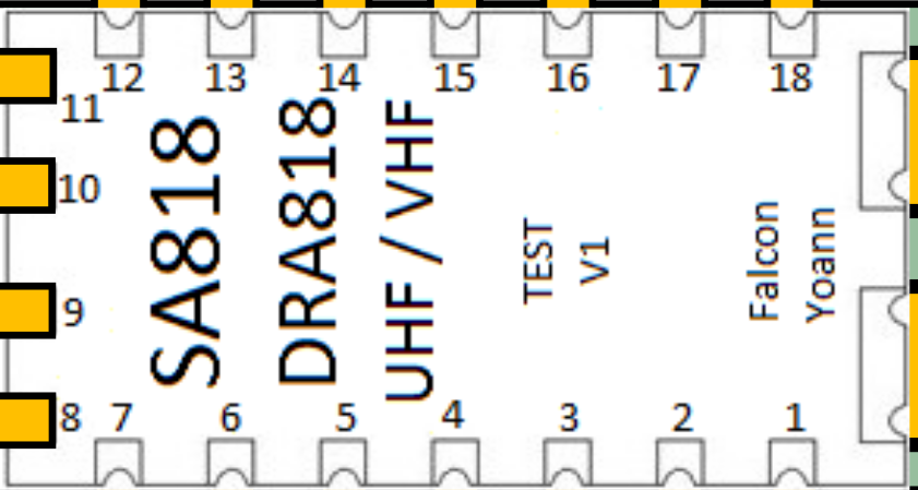
Pin Configuration and Descriptions
| Pin Number | Pin Name | Description |
|---|---|---|
| 1 | VCC | Power Supply (3.3V - 5.5V) |
| 2 | GND | Ground |
| 3 | TXD | Transmit Data (UART) |
| 4 | RXD | Receive Data (UART) |
| 5 | PTT | Push-to-Talk (Active Low) |
| 6 | MIC | Microphone Input |
| 7 | SPK | Speaker Output |
| 8 | SQL | Squelch Control |
| 9 | NC | Not Connected |
| 10 | NC | Not Connected |
Usage Instructions
How to Use the SA818s-VHF in a Circuit
- Power Supply: Connect the VCC pin to a stable power supply within the range of 3.3V to 5.5V. Connect the GND pin to the ground of your circuit.
- UART Communication: Connect the TXD pin to the RX pin of your microcontroller (e.g., Arduino UNO) and the RXD pin to the TX pin of your microcontroller.
- Audio Connections: Connect a microphone to the MIC pin and a speaker to the SPK pin for audio input and output.
- Push-to-Talk (PTT): Connect a switch between the PTT pin and GND. When the switch is closed, the module will enter transmit mode.
- Squelch Control: The SQL pin can be used to control the squelch level. This pin can be left unconnected if not used.
Important Considerations and Best Practices
- Power Supply: Ensure that the power supply is stable and within the specified range to avoid damage to the module.
- Antenna: Use a proper VHF antenna to ensure optimal performance. The antenna should be matched to the frequency range of the module.
- Heat Dissipation: The module can get warm during operation, especially in transmit mode. Ensure adequate ventilation or heat sinking if used in a confined space.
- Interference: Avoid placing the module near sources of electromagnetic interference to maintain signal integrity.
Example Code for Arduino UNO
#include <SoftwareSerial.h>

// Define the pins for SoftwareSerial
#define RX_PIN 10
#define TX_PIN 11
#define PTT_PIN 12

SoftwareSerial sa818sSerial(RX_PIN, TX_PIN);

void setup() {
  // Initialize the serial communication with the SA818s-VHF module
  sa818sSerial.begin(9600);
  // Initialize the serial communication with the computer
  Serial.begin(9600);
  // Set the PTT pin as output
  pinMode(PTT_PIN, OUTPUT);
  // Set the PTT pin to HIGH (idle state)
  digitalWrite(PTT_PIN, HIGH);
}

void loop() {
  // Check if data is available from the computer
  if (Serial.available()) {
    // Read the data from the computer
    char data = Serial.read();
    // Send the data to the SA818s-VHF module
    sa818sSerial.write(data);
  }

  // Check if data is available from the SA818s-VHF module
  if (sa818sSerial.available()) {
    // Read the data from the SA818s-VHF module
    char data = sa818sSerial.read();
    // Send the data to the computer
    Serial.write(data);
  }
}
Troubleshooting and FAQs
Common Issues and Solutions
No Transmission or Reception:
- Solution: Check the power supply and ensure it is within the specified range. Verify the connections, especially the antenna, and ensure the PTT pin is properly connected.
Poor Audio Quality:
- Solution: Ensure the microphone and speaker are properly connected. Check for any sources of interference and ensure the antenna is properly matched to the frequency range.
Module Overheating:
- Solution: Ensure adequate ventilation and consider adding a heat sink if the module is used in a confined space or for extended periods.
FAQs
Can I use the SA818s-VHF with a 3.3V microcontroller?
- Yes, the SA818s-VHF can operate with a power supply range of 3.3V to 5.5V, making it compatible with both 3.3V and 5V microcontrollers.
What type of antenna should I use?
- Use a VHF antenna that is matched to the frequency range of 134-174 MHz for optimal performance.
How do I adjust the squelch level?
- The squelch level can be adjusted using the SQL pin. Refer to the module's datasheet for detailed instructions on squelch control.
By following this documentation, users can effectively integrate and utilize the SA818s-VHF transceiver module in their wireless communication projects.