How to Use RUT955: Examples, Pinouts, and Specs
Introduction
The RUT955 is a robust industrial router manufactured by Teltonika, designed for secure and reliable wireless communication in IoT applications. It supports multiple connectivity options, including LTE, Ethernet, and Wi-Fi, making it a versatile solution for remote monitoring, control, and data transmission in industrial, commercial, and residential environments.
This router is particularly well-suited for applications such as:
- Industrial automation and control systems
- Remote monitoring of sensors and devices
- Smart transportation and fleet management
- Renewable energy systems (e.g., solar or wind monitoring)
- Retail and Point-of-Sale (POS) systems
Explore Projects Built with RUT955


Explore Projects Built with RUT955
Technical Specifications
Key Technical Details
| Parameter | Specification |
|---|---|
| Manufacturer | Teltonika |
| Part ID | RUT955 |
| Cellular Connectivity | LTE Cat 4 (up to 150 Mbps download, 50 Mbps upload) |
| Wi-Fi | IEEE 802.11b/g/n, 2.4 GHz |
| Ethernet Ports | 4 x 10/100 Mbps (1 WAN, 3 LAN) |
| Serial Ports | 1 x RS232, 1 x RS485 |
| GNSS Support | GPS, GLONASS, BeiDou |
| Input Voltage Range | 9 V to 30 V DC |
| Power Consumption | < 7 W (typical) |
| Operating Temperature Range | -40°C to +75°C |
| Dimensions | 110 mm x 100 mm x 50 mm |
| Certifications | CE, RoHS, E-Mark, FCC, PTCRB |
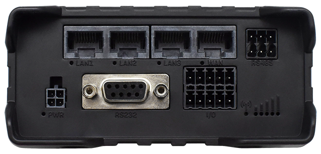
Pin Configuration and Descriptions
The RUT955 features multiple interfaces for connectivity and control. Below is a summary of its key ports and their functions:
Power and I/O Ports
| Pin/Port | Description |
|---|---|
| Power Input | 2-pin terminal block for DC power input (9 V to 30 V) |
| Digital I/O | 4 configurable digital inputs/outputs for monitoring or control |
| USB Port | 1 x USB 2.0 for external device connection |
Communication Interfaces
| Port | Description |
|---|---|
| Ethernet WAN | 1 x 10/100 Mbps Ethernet port for WAN connection |
| Ethernet LAN | 3 x 10/100 Mbps Ethernet ports for LAN devices |
| RS232 | Serial communication port for legacy devices |
| RS485 | Serial communication port for industrial devices |
| SIM Slots | 2 x Mini-SIM slots for dual SIM functionality |
Antenna Connectors
| Connector | Description |
|---|---|
| LTE Main/Backup | 2 x SMA connectors for LTE antennas |
| Wi-Fi | 1 x RP-SMA connector for Wi-Fi antenna |
| GNSS | 1 x SMA connector for GPS/GNSS antenna |
Usage Instructions
How to Use the RUT955 in a Network
Powering the Device:
- Connect a DC power supply (9 V to 30 V) to the power input terminal block.
- Ensure the power source is stable and within the specified voltage range.
Connecting to the Internet:
- Insert a SIM card into one of the SIM slots for LTE connectivity.
- Alternatively, connect the WAN port to an existing Ethernet network.
Configuring the Router:
- Connect a computer to one of the LAN ports or via Wi-Fi.
- Access the web interface by entering the default IP address (192.168.1.1) in a browser.
- Log in using the default credentials (username:
admin, password:admin01). - Follow the setup wizard to configure network settings, security, and other parameters.
Connecting Devices:
- Use the LAN ports, Wi-Fi, or serial interfaces (RS232/RS485) to connect devices.
- Configure digital I/O ports for monitoring or controlling external equipment.
Important Considerations and Best Practices
- Antenna Placement: Ensure that LTE, Wi-Fi, and GNSS antennas are securely connected and positioned for optimal signal strength.
- Firmware Updates: Regularly update the firmware to ensure the latest features and security patches are applied.
- Power Supply: Use a stable and clean power source to avoid disruptions or damage to the device.
- Environmental Conditions: Install the router in a location that adheres to the operating temperature and humidity specifications.
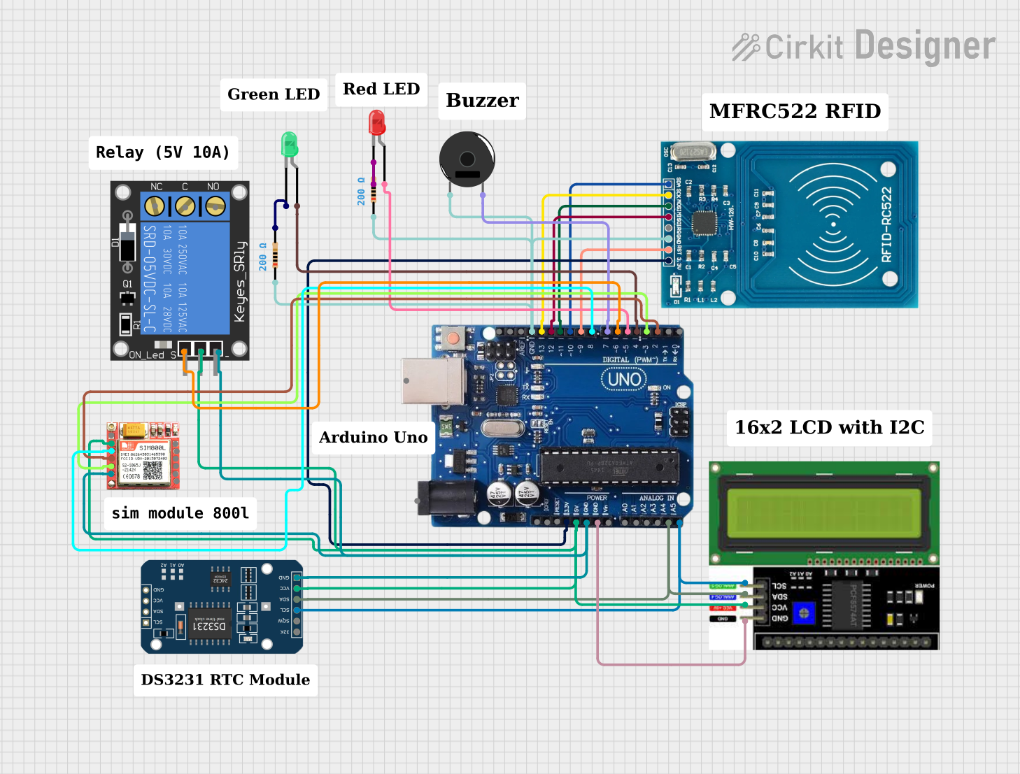
Example: Connecting to an Arduino UNO
The RUT955 can be used to send data from an Arduino UNO to a remote server via LTE. Below is an example of Arduino code to send sensor data over a serial connection to the RUT955:
#include <SoftwareSerial.h>

// Define RX and TX pins for SoftwareSerial
SoftwareSerial mySerial(10, 11); // RX = pin 10, TX = pin 11

void setup() {
  // Initialize serial communication with Arduino and RUT955
  Serial.begin(9600); // Arduino Serial Monitor
  mySerial.begin(9600); // Communication with RUT955

  // Print a message to indicate setup is complete
  Serial.println("Arduino is ready to send data to RUT955.");
}

void loop() {
  // Example: Send a temperature reading to RUT955
  float temperature = 25.5; // Replace with actual sensor reading
  mySerial.print("Temperature: ");
  mySerial.println(temperature);

  // Wait for 1 second before sending the next reading
  delay(1000);
}
Note: Ensure the RS232 or RS485 interface on the RUT955 is properly configured to receive data from the Arduino.
Troubleshooting and FAQs
Common Issues and Solutions
No Internet Connection:
- Cause: Incorrect SIM card installation or APN settings.
- Solution: Verify the SIM card is properly inserted and configure the correct APN in the web interface.
Unable to Access Web Interface:
- Cause: Incorrect IP address or network configuration.
- Solution: Ensure the computer is on the same subnet as the router (default IP: 192.168.1.1). Reset the router if necessary.
Weak Signal Strength:
- Cause: Poor antenna placement or interference.
- Solution: Reposition the antennas and ensure they are securely connected. Avoid placing the router near metal objects or other sources of interference.
Device Not Powering On:
- Cause: Insufficient or unstable power supply.
- Solution: Check the power source and ensure it meets the voltage and current requirements.
FAQs
Q: Can the RUT955 operate with dual SIM cards?
- A: Yes, the RUT955 supports dual SIM functionality for failover and load balancing.
Q: Is the RUT955 compatible with 5 GHz Wi-Fi?
- A: No, the RUT955 only supports 2.4 GHz Wi-Fi.
Q: How can I reset the router to factory settings?
- A: Press and hold the reset button for 5 seconds until the LEDs start blinking.
Q: Can I use the RUT955 in outdoor environments?
- A: The RUT955 is designed for industrial use but should be installed in a weatherproof enclosure for outdoor applications.