
How to Use CNC SHIELD V3: Examples, Pinouts, and Specs
 Design with CNC SHIELD V3 in Cirkit Designer
Introduction
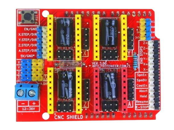
The CNC SHIELD V3, manufactured by INFO PROTONER (Part ID: CNC SHIELD), is a versatile control board designed for CNC machines, 3D printers, and laser engravers. It provides an efficient and compact solution for controlling stepper motors and other components in these systems. The shield is compatible with Arduino boards, making it easy to program and integrate into various projects. With support for multiple stepper motor drivers and convenient connectivity options, the CNC SHIELD V3 is ideal for hobbyists and professionals alike.
Explore Projects Built with CNC SHIELD V3
 Open Project in Cirkit Designer
 Open Project in Cirkit Designer
 Open Project in Cirkit Designer
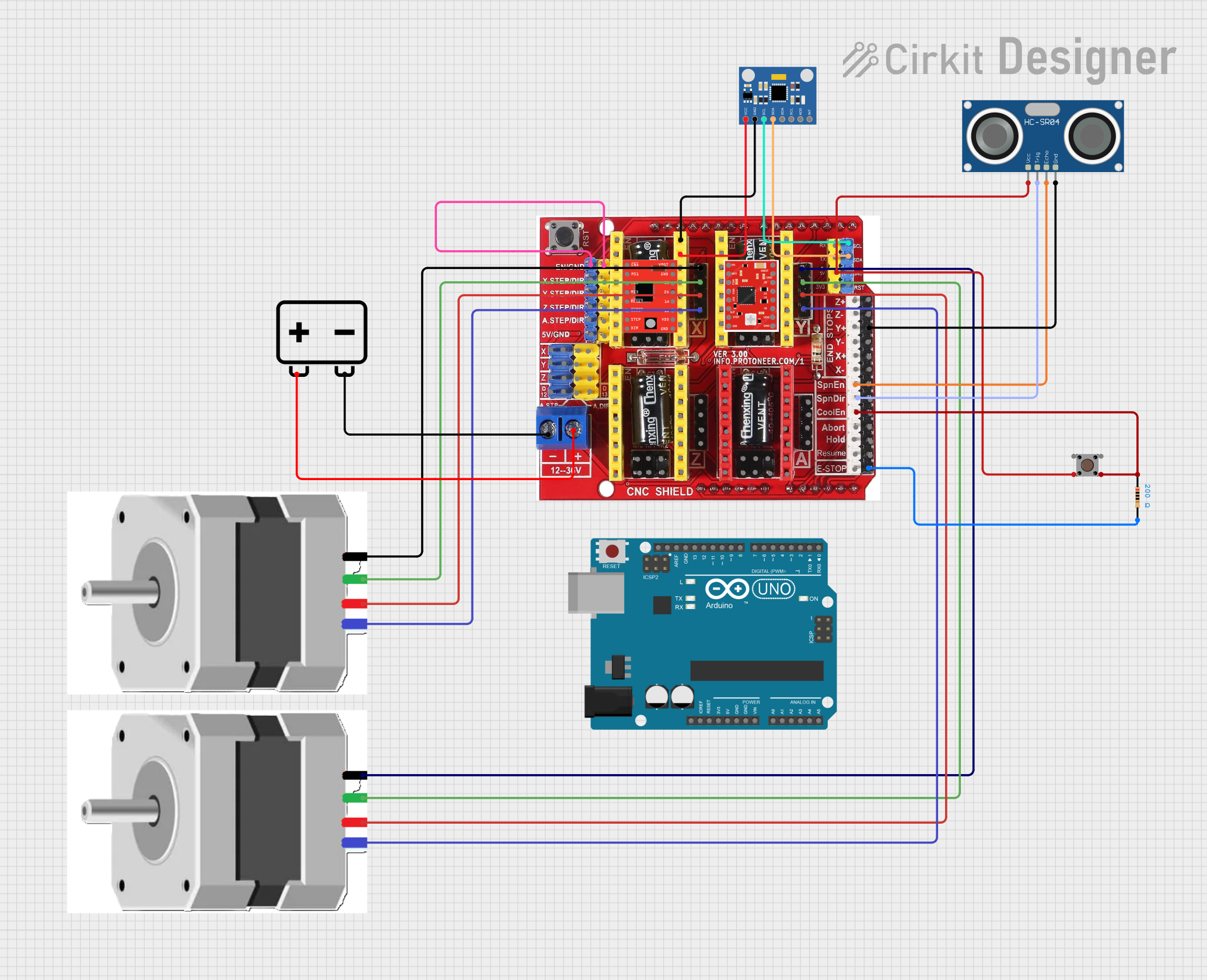 Open Project in Cirkit Designer
Explore Projects Built with CNC SHIELD V3
Open Project in Cirkit DesignerOpen Project in Cirkit DesignerOpen Project in Cirkit DesignerOpen Project in Cirkit DesignerCommon Applications and Use Cases
- CNC milling machines
- 3D printers
- Laser engravers
- Robotics and automation projects
- DIY motion control systems
Technical Specifications
Key Technical Details
- Input Voltage: 12V–36V DC (via external power supply)
- Stepper Motor Driver Compatibility: A4988, DRV8825, and similar modules
- Number of Stepper Motor Axes Supported: 4 (X, Y, Z, and A)
- Microstepping Support: Configurable via jumpers
- Communication Interface: Arduino-compatible pins
- Endstop Support: 6 endstop connections (2 per axis: min and max)
- Spindle/Accessory Control: PWM output for spindle or laser control
- Dimensions: 69mm x 54mm (approx.)
Pin Configuration and Descriptions
The CNC SHIELD V3 features a standard pin layout for easy integration with Arduino boards. Below is the pin configuration:
Stepper Motor Driver Pins
| Pin Name | Description |
|---|---|
| VMOT | Power input for stepper motors (12V–36V DC) |
| GND | Ground connection for stepper motor power |
| STEP | Step signal input for controlling motor steps |
| DIR | Direction signal input for controlling motor rotation direction |
| EN | Enable signal input to activate or deactivate the motor driver |
Endstop Pins
| Pin Name | Description |
|---|---|
| X-MIN, X-MAX | Endstop connections for the X-axis (minimum and maximum positions) |
| Y-MIN, Y-MAX | Endstop connections for the Y-axis (minimum and maximum positions) |
| Z-MIN, Z-MAX | Endstop connections for the Z-axis (minimum and maximum positions) |
Other Pins
| Pin Name | Description |
|---|---|
| SPNEN | Spindle enable signal |
| SPNDIR | Spindle direction signal |
| PWM | Pulse-width modulation output for spindle or laser control |
| GRBL Pins | Arduino-compatible pins for GRBL firmware communication |
Usage Instructions
How to Use the CNC SHIELD V3 in a Circuit
Connect the Shield to an Arduino Board:
- Align the CNC SHIELD V3 with the Arduino UNO and plug it in securely.
- Ensure the pins are properly aligned to avoid damage.
Install Stepper Motor Drivers:
- Insert compatible stepper motor driver modules (e.g., A4988 or DRV8825) into the designated sockets.
- Ensure correct orientation by matching the
EN,STEP, andDIRpins.
Connect Stepper Motors:
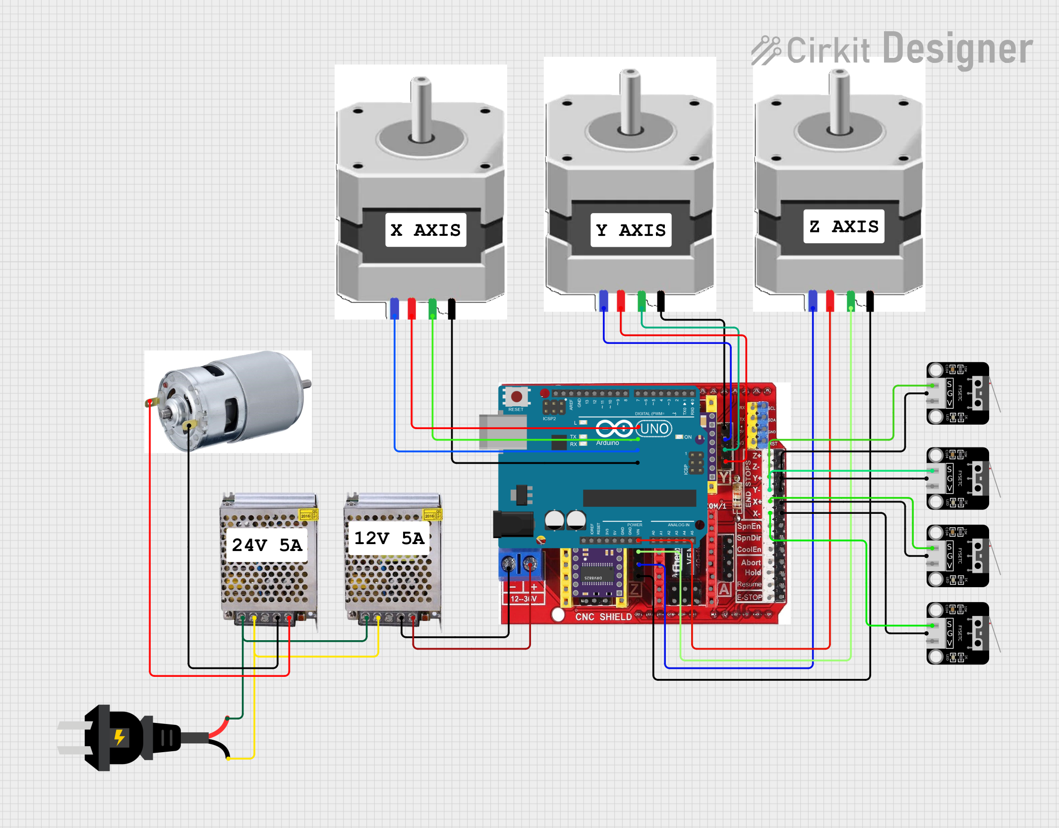
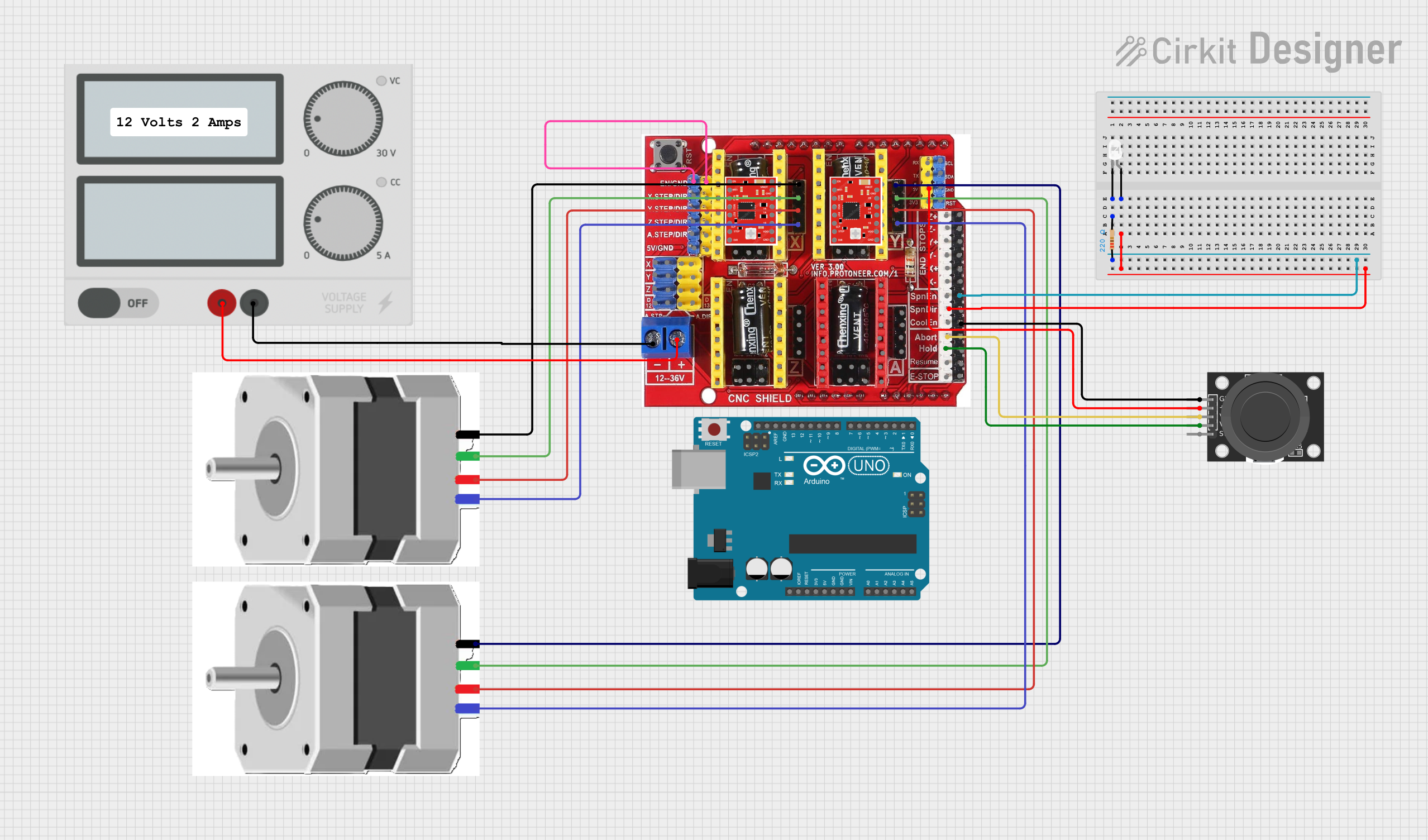
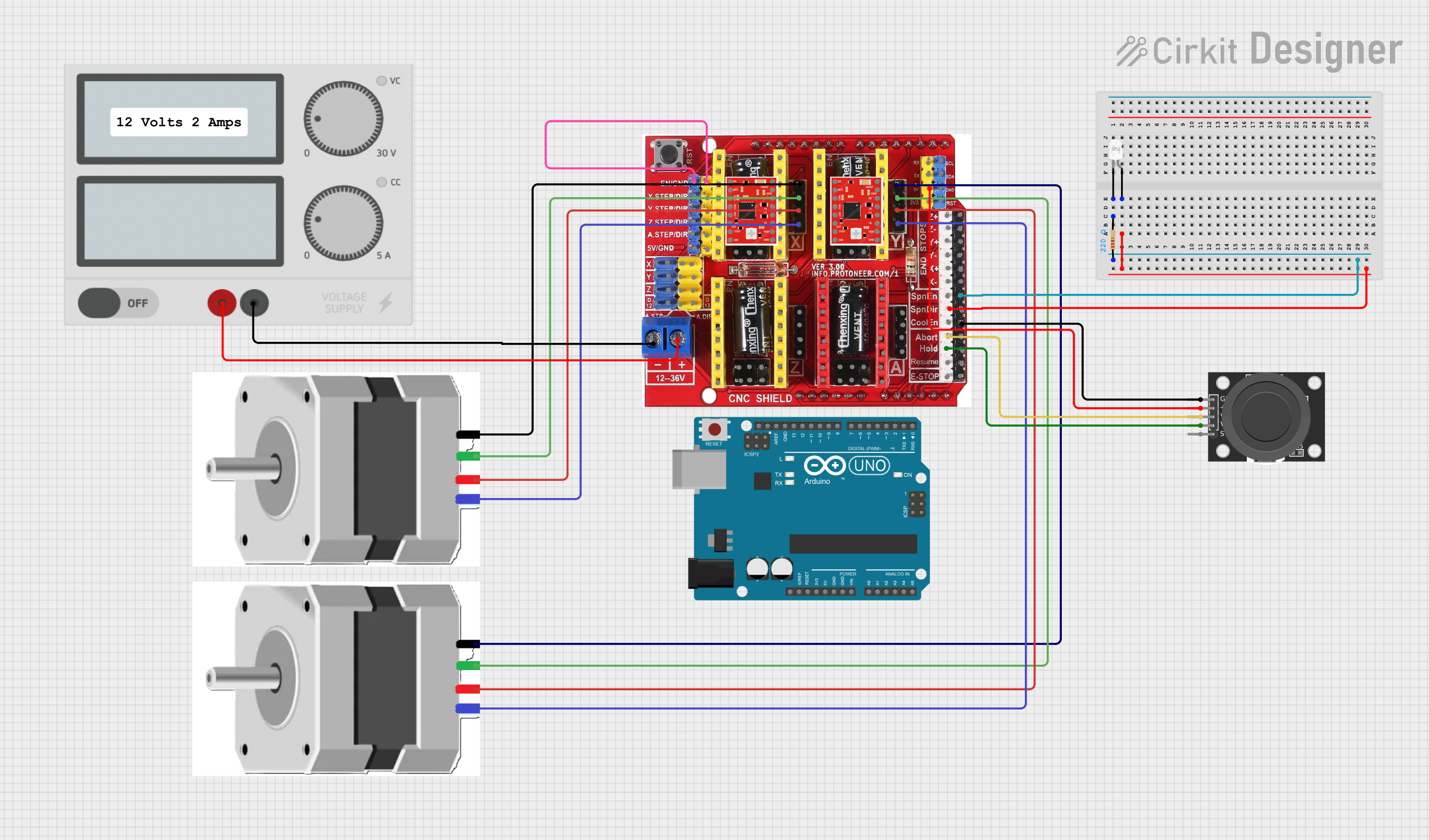
- Attach the stepper motor wires to the corresponding motor output terminals (X, Y, Z, or A).
- Double-check the wiring to match the motor's datasheet.
Power the Shield:
- Connect a 12V–36V DC power supply to the
VMOTandGNDterminals. - Ensure the power supply meets the current requirements of your motors.
- Connect a 12V–36V DC power supply to the
Configure Microstepping:
- Use the jumpers beneath each stepper driver to set the desired microstepping mode.
- Refer to the stepper driver datasheet for jumper settings.
Connect Endstops and Accessories:
- Attach endstop switches to the
X-MIN,X-MAX,Y-MIN,Y-MAX,Z-MIN, andZ-MAXpins as needed. - Connect a spindle or laser to the
PWMandSPNENpins for accessory control.
- Attach endstop switches to the
Upload GRBL Firmware:
- Install the GRBL firmware on your Arduino board using the Arduino IDE.
- Configure GRBL settings to match your machine's specifications.
Important Considerations and Best Practices
- Cooling: Ensure proper cooling for stepper motor drivers, especially when driving high-current motors. Use heatsinks and/or a cooling fan.
- Power Supply: Use a stable and adequately rated power supply to avoid voltage drops or overheating.
- Driver Orientation: Double-check the orientation of stepper motor drivers before powering the shield to prevent damage.
- Firmware Configuration: Adjust GRBL settings (e.g., steps/mm, max feed rate) to suit your machine's hardware.
Example Code for Arduino UNO
Below is an example of how to control a stepper motor connected to the CNC SHIELD V3 using GRBL firmware:
// This example assumes GRBL firmware is installed on the Arduino UNO.
// GRBL handles stepper motor control, so no additional code is needed
// for basic operation. Use a G-code sender to send commands to the shield.

// Example G-code commands:
// G0 X10 Y10 Z5  ; Move to X=10, Y=10, Z=5
// G1 X20 F1000   ; Linear move to X=20 at feed rate of 1000 mm/min
// M3 S1000       ; Turn on spindle/laser at 1000 PWM
// M5             ; Turn off spindle/laser
Troubleshooting and FAQs
Common Issues and Solutions
Stepper Motors Not Moving:
- Cause: Incorrect wiring or driver orientation.
- Solution: Verify motor wiring and ensure drivers are installed correctly.
Overheating Drivers:
- Cause: Insufficient cooling or excessive current settings.
- Solution: Add heatsinks or a cooling fan, and adjust the current limit on the drivers.
Endstops Not Detected:
- Cause: Faulty wiring or incorrect GRBL configuration.
- Solution: Check endstop connections and ensure GRBL settings (
$5and$21) are configured correctly.
Spindle/Laser Not Responding:
- Cause: Incorrect PWM or SPNEN wiring.
- Solution: Verify connections and ensure GRBL spindle settings (
$30,$31,$32) are properly configured.
FAQs
Q: Can I use the CNC SHIELD V3 with an Arduino Mega?
A: The CNC SHIELD V3 is designed for Arduino UNO, but it can be adapted for Mega with custom wiring.Q: What stepper motor drivers are compatible?
A: The shield supports A4988, DRV8825, and similar stepper motor drivers.Q: How do I reset GRBL settings?
A: Send the$RST=*command via a G-code sender to reset GRBL to factory defaults.Q: Can I control a 4th axis with this shield?
A: Yes, theAaxis can be used for a 4th stepper motor, such as a rotary axis.
This concludes the CNC SHIELD V3 documentation. For further assistance, refer to the INFO PROTONER user manual or community forums.