
How to Use LCD ESP32-4827S043: Examples, Pinouts, and Specs
 Design with LCD ESP32-4827S043 in Cirkit Designer
Introduction
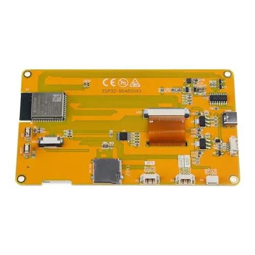
The LCD ESP32-4827S043 is a liquid crystal display (LCD) module specifically designed for seamless integration with the ESP32 microcontroller. Featuring a 4.3-inch screen, this module is ideal for creating user interfaces, displaying real-time data, and enhancing the visual experience in embedded systems. Its compatibility with the ESP32 makes it a versatile choice for IoT projects, industrial automation, and consumer electronics.
Explore Projects Built with LCD ESP32-4827S043
 Open Project in Cirkit Designer
 Open Project in Cirkit Designer
 Open Project in Cirkit Designer
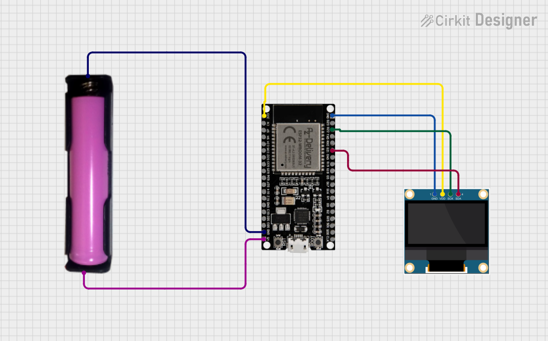 Open Project in Cirkit Designer
Explore Projects Built with LCD ESP32-4827S043
Open Project in Cirkit DesignerOpen Project in Cirkit DesignerOpen Project in Cirkit DesignerOpen Project in Cirkit DesignerCommon Applications
- User interfaces for IoT devices
- Data visualization in industrial systems
- Smart home control panels
- Educational and prototyping projects
- Real-time monitoring dashboards
Technical Specifications
Key Technical Details
| Parameter | Specification |
|---|---|
| Screen Size | 4.3 inches |
| Resolution | 480 x 272 pixels |
| Display Type | TFT LCD |
| Interface | SPI (Serial Peripheral Interface) |
| Operating Voltage | 3.3V |
| Backlight | LED |
| Touchscreen Support | Capacitive (optional) |
| Controller IC | ILI9488 |
| Operating Temperature | -20°C to 70°C |
| Dimensions | 105.5mm x 67.2mm x 4.5mm |
Pin Configuration and Descriptions
The LCD ESP32-4827S043 module typically uses an SPI interface for communication. Below is the pin configuration:
| Pin Name | Pin Number | Description |
|---|---|---|
| VCC | 1 | Power supply input (3.3V) |
| GND | 2 | Ground |
| CS | 3 | Chip Select (active low) |
| SCK | 4 | Serial Clock (SPI clock input) |
| MOSI | 5 | Master Out Slave In (SPI data input) |
| MISO | 6 | Master In Slave Out (SPI data output, optional) |
| DC | 7 | Data/Command control pin |
| RESET | 8 | Reset signal (active low) |
| BLK | 9 | Backlight control (PWM or ON/OFF) |
| T_IRQ | 10 | Touchscreen interrupt (if touchscreen is used) |
Usage Instructions
How to Use the Component in a Circuit
- Power Supply: Connect the
VCCpin to a 3.3V power source and theGNDpin to ground. - SPI Communication: Connect the
CS,SCK, andMOSIpins to the corresponding SPI pins on the ESP32. If required, connect theMISOpin for bidirectional communication. - Control Pins:
- Use the
DCpin to toggle between data and command modes. - Connect the
RESETpin to an ESP32 GPIO pin for resetting the display.
- Use the
- Backlight: The
BLKpin can be connected to a PWM-capable GPIO pin on the ESP32 to control the brightness of the backlight. - Touchscreen (Optional): If the module includes a touchscreen, connect the
T_IRQpin to an interrupt-capable GPIO pin on the ESP32.
Example Code for Arduino IDE
Below is an example of how to initialize and use the LCD ESP32-4827S043 with the ESP32 using the Arduino IDE. This example uses the TFT_eSPI library.
#include <TFT_eSPI.h> // Include the TFT_eSPI library

TFT_eSPI tft = TFT_eSPI(); // Create an instance of the TFT_eSPI class

void setup() {
  tft.init(); // Initialize the display
  tft.setRotation(1); // Set screen orientation (0-3)
  tft.fillScreen(TFT_BLACK); // Clear the screen with black color

  // Display a message
  tft.setTextColor(TFT_WHITE, TFT_BLACK); // Set text color and background
  tft.setTextSize(2); // Set text size
  tft.setCursor(10, 10); // Set cursor position
  tft.println("Hello, ESP32!"); // Print text to the screen
}

void loop() {
  // Add your code here to update the display
}
Important Considerations and Best Practices
- Voltage Levels: Ensure the module is powered with 3.3V. Using higher voltages may damage the display.
- SPI Speed: Configure the SPI clock speed appropriately. A typical value is 40 MHz, but this may vary depending on the specific application.
- Backlight Control: Use PWM to adjust the backlight brightness for power efficiency.
- Touchscreen Calibration: If using the touchscreen, ensure proper calibration for accurate touch detection.
- Library Compatibility: Use a compatible library like
TFT_eSPIorAdafruit_GFXfor easier integration.
Troubleshooting and FAQs
Common Issues and Solutions
Display Not Turning On:
- Verify the power connections (
VCCandGND). - Check the
RESETpin connection and ensure it is not held low.
- Verify the power connections (
No Output on the Screen:
- Ensure the SPI connections (
CS,SCK,MOSI) are correct. - Verify that the
DCpin is toggling correctly between data and command modes.
- Ensure the SPI connections (
Flickering or Dim Backlight:
- Check the
BLKpin connection. If using PWM, ensure the duty cycle is set correctly. - Verify the power supply voltage and current capacity.
- Check the
Touchscreen Not Responding:
- Ensure the
T_IRQpin is connected to an interrupt-capable GPIO pin. - Check if the touchscreen requires additional drivers or calibration.
- Ensure the
FAQs
Q: Can I use this display with a 5V microcontroller?
A: No, the LCD ESP32-4827S043 is designed for 3.3V operation. Use a level shifter if interfacing with a 5V microcontroller.
Q: What is the maximum SPI clock speed supported?
A: The module typically supports SPI clock speeds up to 40 MHz. Refer to the controller IC datasheet for exact details.
Q: Does the module support multitouch?
A: No, the optional touchscreen supports single-touch functionality only.
Q: Can I use this display without a touchscreen?
A: Yes, the touchscreen is optional, and the display can function independently.
By following this documentation, you can effectively integrate and utilize the LCD ESP32-4827S043 in your projects.