
How to Use waveshare bus servo driver: Examples, Pinouts, and Specs
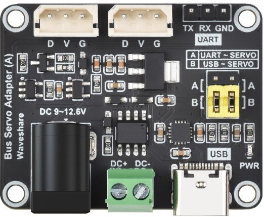
 Design with waveshare bus servo driver in Cirkit Designer
Introduction
The Waveshare Bus Servo Driver is a specialized driver designed to control multiple servos via a bus interface. It enables precise positioning and movement, making it ideal for robotics, automation, and other applications requiring synchronized servo control. This driver simplifies the process of managing multiple servos by using a single communication bus, reducing wiring complexity and improving scalability.
Explore Projects Built with waveshare bus servo driver
 Open Project in Cirkit Designer
 Open Project in Cirkit Designer
 Open Project in Cirkit Designer
 Open Project in Cirkit Designer
Explore Projects Built with waveshare bus servo driver
Open Project in Cirkit DesignerOpen Project in Cirkit DesignerOpen Project in Cirkit DesignerOpen Project in Cirkit DesignerCommon Applications and Use Cases
- Robotics: Controlling robotic arms, legs, or grippers.
- Automation: Managing servo-driven mechanisms in industrial systems.
- Animatronics: Creating lifelike movements in animatronic models.
- Educational Projects: Teaching servo control and bus communication concepts.
- DIY Projects: Building custom servo-controlled devices.
Technical Specifications
The Waveshare Bus Servo Driver is designed to work seamlessly with a variety of bus servos. Below are its key technical details:
Key Technical Details
| Parameter | Specification |
|---|---|
| Operating Voltage | 6V to 12V |
| Communication Protocol | UART (TTL level) |
| Control Channels | Up to 253 servos |
| Baud Rate | 115200 bps (default, configurable) |
| Dimensions | 65mm x 50mm |
| Weight | 20g |
| Operating Temperature | -20°C to 60°C |
Pin Configuration and Descriptions
The Waveshare Bus Servo Driver features a simple pin layout for easy integration. Below is the pin configuration:
| Pin Name | Description |
|---|---|
| VIN | Power input (6V to 12V) |
| GND | Ground |
| TX | UART transmit pin (connect to RX of controller) |
| RX | UART receive pin (connect to TX of controller) |
| BUS+ | Positive bus line for servo communication |
| BUS- | Negative bus line for servo communication |
Usage Instructions
How to Use the Component in a Circuit
- Power Supply: Connect the VIN and GND pins to a stable power source (6V to 12V). Ensure the power supply can handle the total current draw of all connected servos.
- UART Connection: Connect the TX pin of the driver to the RX pin of your microcontroller (e.g., Arduino UNO) and the RX pin of the driver to the TX pin of the microcontroller.
- Servo Bus Connection: Connect the BUS+ and BUS- pins to the corresponding bus lines of your servos.
- Programming: Use the UART interface to send commands to the driver, which will control the connected servos.
Important Considerations and Best Practices
- Power Supply: Ensure the power supply voltage matches the requirements of your servos. Overvoltage can damage the servos or the driver.
- Baud Rate: The default baud rate is 115200 bps. If needed, configure the baud rate to match your system requirements.
- Servo Addressing: Each servo on the bus must have a unique ID. Use the manufacturer's software or commands to set unique IDs before connecting multiple servos.
- Wiring: Keep the bus lines as short as possible to minimize signal degradation. Use shielded cables in noisy environments.
Example Code for Arduino UNO
Below is an example code snippet to control a servo using the Waveshare Bus Servo Driver and an Arduino UNO:
#include <SoftwareSerial.h>

// Define RX and TX pins for SoftwareSerial
SoftwareSerial busServoSerial(10, 11); // RX = pin 10, TX = pin 11

void setup() {
  busServoSerial.begin(115200); // Initialize UART at 115200 bps
  Serial.begin(9600);           // Initialize Serial Monitor for debugging

  // Example: Move servo with ID 1 to position 500 (range: 0-1000)
  moveServo(1, 500);
}

void loop() {
  // Add your main code here
}

// Function to send a command to move a servo
void moveServo(uint8_t servoID, uint16_t position) {
  uint8_t command[7];
  command[0] = 0x55; // Header byte 1
  command[1] = 0x55; // Header byte 2
  command[2] = servoID; // Servo ID
  command[3] = 0x07; // Length of the command
  command[4] = 0x03; // Command type: Move
  command[5] = position & 0xFF; // Low byte of position
  command[6] = (position >> 8) & 0xFF; // High byte of position

  busServoSerial.write(command, 7); // Send the command
  Serial.println("Command sent to servo.");
}
Troubleshooting and FAQs
Common Issues and Solutions
Servos Not Responding:
- Cause: Incorrect wiring or power supply issues.
- Solution: Double-check all connections and ensure the power supply meets the voltage and current requirements.
Communication Errors:
- Cause: Mismatched baud rate or incorrect UART connections.
- Solution: Verify that the baud rate is set to 115200 bps (or the configured value) and ensure TX and RX pins are correctly connected.
Multiple Servos Not Working:
- Cause: Duplicate servo IDs or insufficient power.
- Solution: Assign unique IDs to each servo and ensure the power supply can handle the total current draw.
Servo Jittering:
- Cause: Electrical noise or unstable power supply.
- Solution: Use a decoupling capacitor near the driver and ensure a stable power source.
FAQs
Q: Can I use this driver with non-bus servos?
A: No, this driver is specifically designed for bus servos. Non-bus servos require individual PWM signals.
Q: How many servos can I connect to this driver?
A: You can connect up to 253 servos, provided the power supply can handle the total current draw.
Q: Can I change the baud rate?
A: Yes, the baud rate is configurable. Refer to the manufacturer's documentation for instructions on changing it.
Q: What is the maximum cable length for the servo bus?
A: The maximum cable length depends on the environment and cable quality. For best results, keep the bus lines as short as possible and use shielded cables in noisy environments.