How to Use DB37: Examples, Pinouts, and Specs
Introduction
The DB37 is a 37-pin D-subminiature (D-sub) connector widely used for serial and parallel communication in various applications. Its robust design and high pin count make it suitable for transmitting multiple signals simultaneously, making it a popular choice in computer systems, industrial equipment, and test instrumentation. The DB37 connector is available in both male and female configurations and is typically used with shielded cables to minimize electromagnetic interference (EMI).
Explore Projects Built with DB37


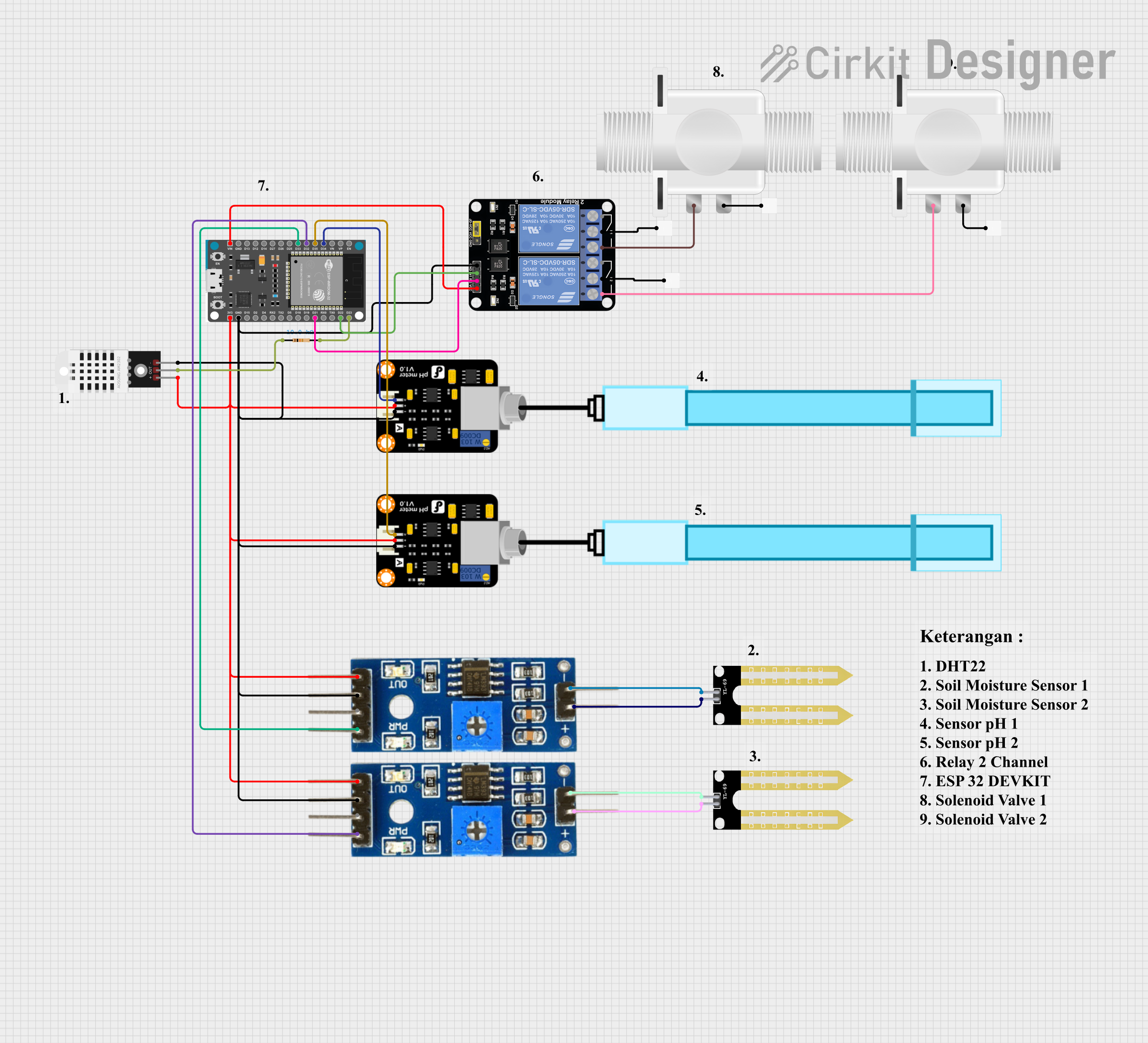
Explore Projects Built with DB37
Common Applications and Use Cases
- Serial and parallel communication in computer systems
- Industrial automation and control systems
- Test and measurement equipment
- Data acquisition systems
- CNC machines and robotics
- Audio and video signal transmission
Technical Specifications
Key Technical Details
- Connector Type: D-subminiature (DB)
- Number of Pins: 37
- Pin Spacing: 2.77 mm (0.109 inches)
- Shell Material: Metal (typically steel or zinc-plated for durability)
- Contact Material: Gold- or tin-plated copper alloy
- Current Rating: Typically 5A per pin (varies by manufacturer)
- Voltage Rating: Up to 300V (varies by manufacturer)
- Operating Temperature: -55°C to +105°C
- Mounting Style: Panel mount or cable mount
- Termination Style: Solder cup, crimp, or PCB mount
Pin Configuration and Descriptions
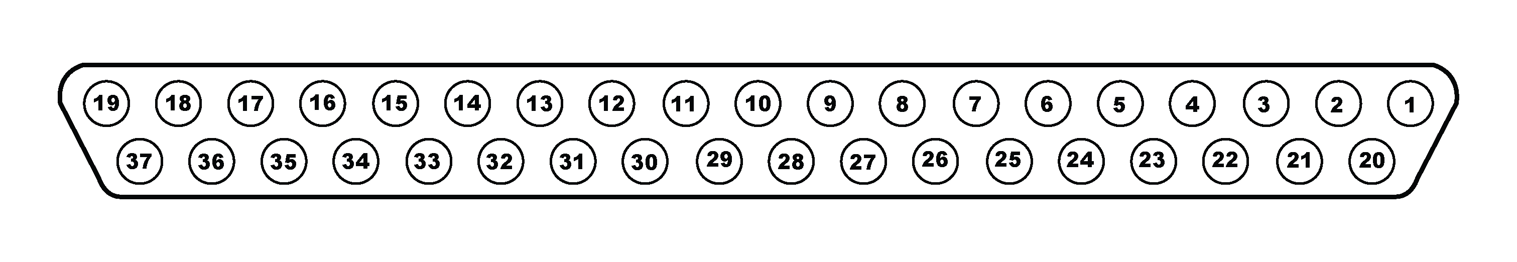
The DB37 connector has 37 pins arranged in two rows: 19 pins in the top row and 18 pins in the bottom row. The pin numbering starts from the top-left corner and proceeds sequentially.
| Pin Number | Description | Common Use |
|---|---|---|
| 1-19 | Signal or data lines | Transmitting/receiving signals |
| 20-37 | Signal or ground lines | Ground or additional signals |
Note: The specific pin assignments depend on the application and protocol being used. Always refer to the device's datasheet or user manual for exact pinout details.
Usage Instructions
How to Use the DB37 in a Circuit
- Identify the Pinout: Refer to the datasheet or application-specific documentation to determine the pin assignments for your DB37 connector.
- Choose the Termination Style: Depending on your application, select a solder cup, crimp, or PCB-mount DB37 connector.
- Prepare the Cable:
- Use a shielded cable to reduce EMI.
- Strip the cable insulation and expose the individual wires.
- Connect the Wires:
- For solder cup connectors, solder each wire to the corresponding pin.
- For crimp connectors, use a crimping tool to attach the wires to the pins.
- Assemble the Connector:
- Secure the connector shell to protect the pins and provide strain relief.
- Ensure the shield is properly grounded to the connector shell for EMI protection.
- Mount the Connector:
- For panel-mount connectors, secure the DB37 to the panel using screws.
- For cable-mount connectors, ensure the strain relief is properly tightened.
Important Considerations and Best Practices
- Signal Integrity: Use shielded cables and proper grounding to minimize noise and signal degradation.
- Current and Voltage Ratings: Ensure the current and voltage do not exceed the connector's specifications.
- Pin Mapping: Double-check the pin mapping to avoid incorrect connections that could damage the equipment.
- Connector Orientation: Align the male and female connectors properly to prevent pin damage.
Example: Connecting DB37 to an Arduino UNO
While the DB37 is not directly compatible with the Arduino UNO due to its high pin count, it can be used with external multiplexers or shift registers to interface with the Arduino. Below is an example of how to read data from a DB37 connector using a multiplexer.
// Example: Reading data from a DB37 connector using a 16-channel multiplexer
// This example assumes the DB37 is connected to a multiplexer, and the Arduino
// reads signals from the multiplexer output.

const int muxSignalPin = A0; // Analog pin connected to the multiplexer output
const int s0 = 2;            // Control pin S0 of the multiplexer
const int s1 = 3;            // Control pin S1 of the multiplexer
const int s2 = 4;            // Control pin S2 of the multiplexer
const int s3 = 5;            // Control pin S3 of the multiplexer

void setup() {
  pinMode(s0, OUTPUT);
  pinMode(s1, OUTPUT);
  pinMode(s2, OUTPUT);
  pinMode(s3, OUTPUT);
  Serial.begin(9600); // Initialize serial communication
}

void loop() {
  for (int channel = 0; channel < 16; channel++) {
    // Set the multiplexer control pins to select the channel
    digitalWrite(s0, channel & 0x01);
    digitalWrite(s1, (channel >> 1) & 0x01);
    digitalWrite(s2, (channel >> 2) & 0x01);
    digitalWrite(s3, (channel >> 3) & 0x01);

    // Read the signal from the selected channel
    int signalValue = analogRead(muxSignalPin);
    Serial.print("Channel ");
    Serial.print(channel);
    Serial.print(": ");
    Serial.println(signalValue);

    delay(100); // Small delay for stability
  }
}
Note: This example demonstrates how to read signals from a DB37 connector using a multiplexer. The actual implementation will depend on the specific application and pin assignments.
Troubleshooting and FAQs
Common Issues and Solutions
Loose Connections:
- Issue: Signals are intermittent or not transmitted correctly.
- Solution: Ensure all wires are securely connected to the pins and the connector shell is properly assembled.
Signal Interference:
- Issue: Noise or distortion in the transmitted signals.
- Solution: Use shielded cables and ensure proper grounding of the connector shell.
Incorrect Pin Mapping:
- Issue: Signals are not received as expected.
- Solution: Double-check the pin mapping and ensure the connections match the device's requirements.
Damaged Pins:
- Issue: Pins are bent or broken, causing poor connections.
- Solution: Replace the damaged connector and handle the DB37 with care during assembly.
FAQs
Q: Can the DB37 be used for power transmission?
- A: While the DB37 can handle low-power signals, it is not designed for high-power transmission. Use it primarily for data and control signals.
Q: How do I prevent EMI when using the DB37?
- A: Use shielded cables, ground the connector shell, and avoid running the cable near high-power lines.
Q: Are DB37 connectors standardized?
- A: Yes, the DB37 follows the D-subminiature connector standard, but pin assignments may vary by application. Always refer to the specific device documentation.
Q: Can I use a DB37 connector with fewer than 37 pins?
- A: Yes, unused pins can be left unconnected, but ensure they are not shorted to other pins or the shell.