How to Use Ambient Light Sensor: Examples, Pinouts, and Specs

Introduction
The Ambient Light Sensor (DFRobot SEN0390) is a device designed to measure the intensity of ambient light in the environment. It provides an analog output proportional to the light level, making it ideal for applications requiring automatic brightness adjustment. This sensor is commonly used in automatic lighting systems, display backlighting, and energy-saving devices to optimize performance based on surrounding light conditions.
Explore Projects Built with Ambient Light Sensor
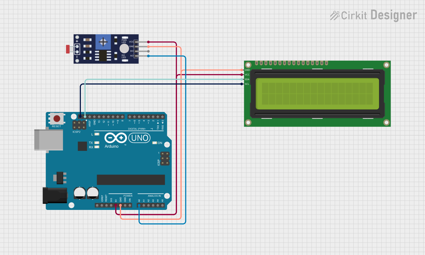
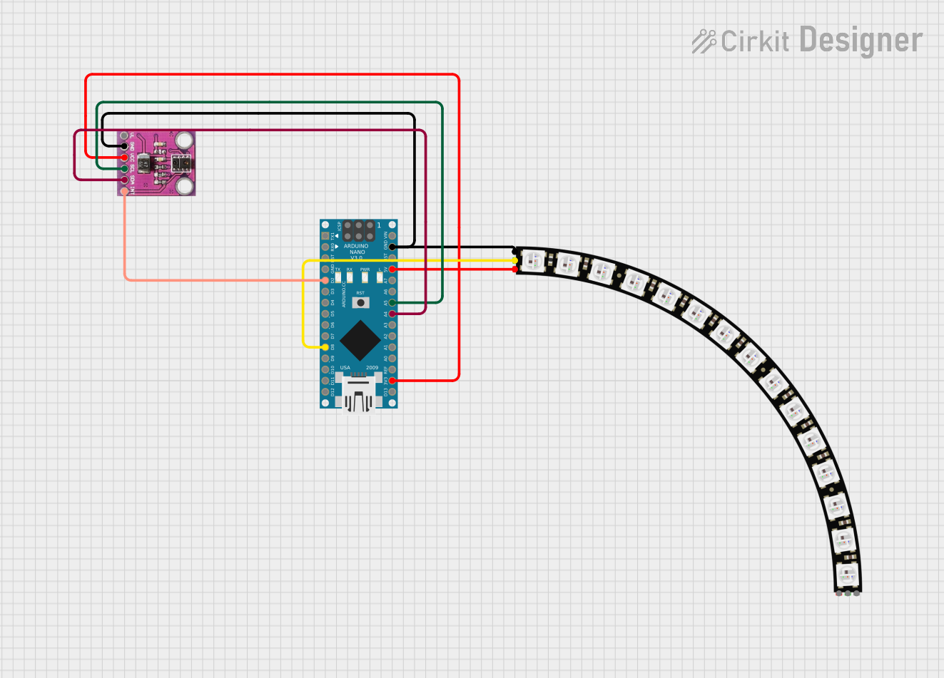

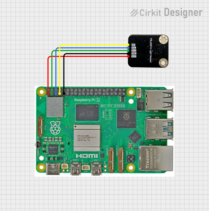
Explore Projects Built with Ambient Light Sensor
Common Applications:
- Automatic brightness adjustment for displays (e.g., smartphones, monitors)
- Smart lighting systems
- Energy-efficient lighting control
- Light intensity monitoring in greenhouses
- IoT devices for environmental sensing
Technical Specifications
The following table outlines the key technical details of the DFRobot SEN0390 Ambient Light Sensor:
| Parameter | Value |
|---|---|
| Manufacturer | DFRobot |
| Part ID | SEN0390 |
| Operating Voltage | 3.3V to 5V |
| Output Type | Analog Voltage |
| Light Intensity Range | 0 to 100,000 lux |
| Response Time | < 15ms |
| Operating Temperature | -40°C to +85°C |
| Dimensions | 22mm x 30mm |
Pin Configuration
The DFRobot SEN0390 has a simple 3-pin interface. The pinout is as follows:
| Pin | Name | Description |
|---|---|---|
| 1 | VCC | Power supply input (3.3V to 5V) |
| 2 | GND | Ground connection |
| 3 | OUT | Analog output voltage proportional to light intensity |
Usage Instructions
Connecting the Sensor
- Power Supply: Connect the
VCCpin to a 3.3V or 5V power source, depending on your system's requirements. - Ground: Connect the
GNDpin to the ground of your circuit. - Output: Connect the
OUTpin to an analog input pin of your microcontroller (e.g., Arduino).
Example Circuit
Below is an example of how to connect the SEN0390 to an Arduino UNO:
VCC→5Vpin on ArduinoGND→GNDpin on ArduinoOUT→A0(analog input pin) on Arduino
Sample Arduino Code
The following code reads the analog output of the sensor and converts it into a light intensity value in lux:
// Define the analog pin connected to the sensor's OUT pin
const int sensorPin = A0;

void setup() {
  Serial.begin(9600); // Initialize serial communication at 9600 baud
}

void loop() {
  int sensorValue = analogRead(sensorPin); // Read the analog value from the sensor
  float voltage = sensorValue * (5.0 / 1023.0); // Convert to voltage (5V system)

  // Convert voltage to light intensity (lux)
  // Note: The conversion factor depends on the sensor's characteristics
  float lightIntensity = voltage * 20000; // Example conversion factor

  // Print the light intensity to the Serial Monitor
  Serial.print("Light Intensity: ");
  Serial.print(lightIntensity);
  Serial.println(" lux");

  delay(500); // Wait for 500ms before the next reading
}
Important Considerations
- Power Supply: Ensure the sensor is powered within its operating voltage range (3.3V to 5V).
- Analog-to-Lux Conversion: The conversion factor from voltage to lux may vary depending on the sensor's calibration. Refer to the manufacturer's datasheet for precise calculations.
- Placement: Avoid placing the sensor in direct sunlight for extended periods, as it may affect accuracy or damage the sensor.
Troubleshooting and FAQs
Common Issues and Solutions
No Output or Incorrect Readings:
- Cause: Incorrect wiring or insufficient power supply.
- Solution: Double-check the connections and ensure the power supply is within the specified range.
Fluctuating Readings:
- Cause: Electrical noise or unstable power supply.
- Solution: Use a decoupling capacitor (e.g., 0.1µF) between
VCCandGNDto stabilize the power supply.
Output Stuck at Maximum or Minimum:
- Cause: Sensor saturation or improper placement.
- Solution: Ensure the sensor is not exposed to extreme light conditions and is placed in an appropriate environment.
FAQs
Q1: Can this sensor be used outdoors?
A1: Yes, the SEN0390 can operate in a wide temperature range (-40°C to +85°C). However, it should be protected from direct exposure to water or extreme sunlight for prolonged periods.
Q2: How do I calibrate the sensor for accurate lux readings?
A2: Calibration involves comparing the sensor's output with a reference lux meter under controlled lighting conditions. Adjust the conversion factor in your code accordingly.
Q3: Can I use this sensor with a 3.3V microcontroller?
A3: Yes, the SEN0390 is compatible with both 3.3V and 5V systems. Ensure the VCC pin is connected to the appropriate voltage source.
By following this documentation, you can effectively integrate the DFRobot SEN0390 Ambient Light Sensor into your projects for reliable light intensity measurements.