Cirkit Designer Logo
Cirkit Designer
Your all-in-one circuit design IDE
Home / 
Component Documentation

How to Use MAX4409: Examples, Pinouts, and Specs
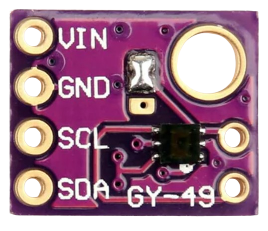
Image of MAX4409
Cirkit Designer LogoDesign with MAX4409 in Cirkit Designer

Introduction

The MAX4409 is an ambient light sensor with an I2C digital output. It features a wide dynamic range and low power consumption, making it suitable for portable devices and display backlighting applications. This sensor is designed to mimic the human eye's response to light, providing accurate measurements across a broad spectrum of lighting conditions.

Explore Projects Built with MAX4409

Use Cirkit Designer to design, explore, and prototype these projects online. Some projects support real-time simulation. Click "Open Project" to start designing instantly!
Cellular-Enabled IoT Device with Real-Time Clock and Power Management
Image of LRCM PHASE 2 BASIC: A project utilizing MAX4409 in a practical application
This circuit features a LilyGo-SIM7000G module for cellular communication and GPS functionality, interfaced with an RTC DS3231 for real-time clock capabilities. It includes voltage sensing through two voltage sensor modules, and uses an 8-channel opto-coupler for isolating different parts of the circuit. Power management is handled by a buck converter connected to a DC power source and batteries, with a fuse for protection and a rocker switch for on/off control. Additionally, there's an LED for indication purposes.
Cirkit Designer LogoOpen Project in Cirkit Designer
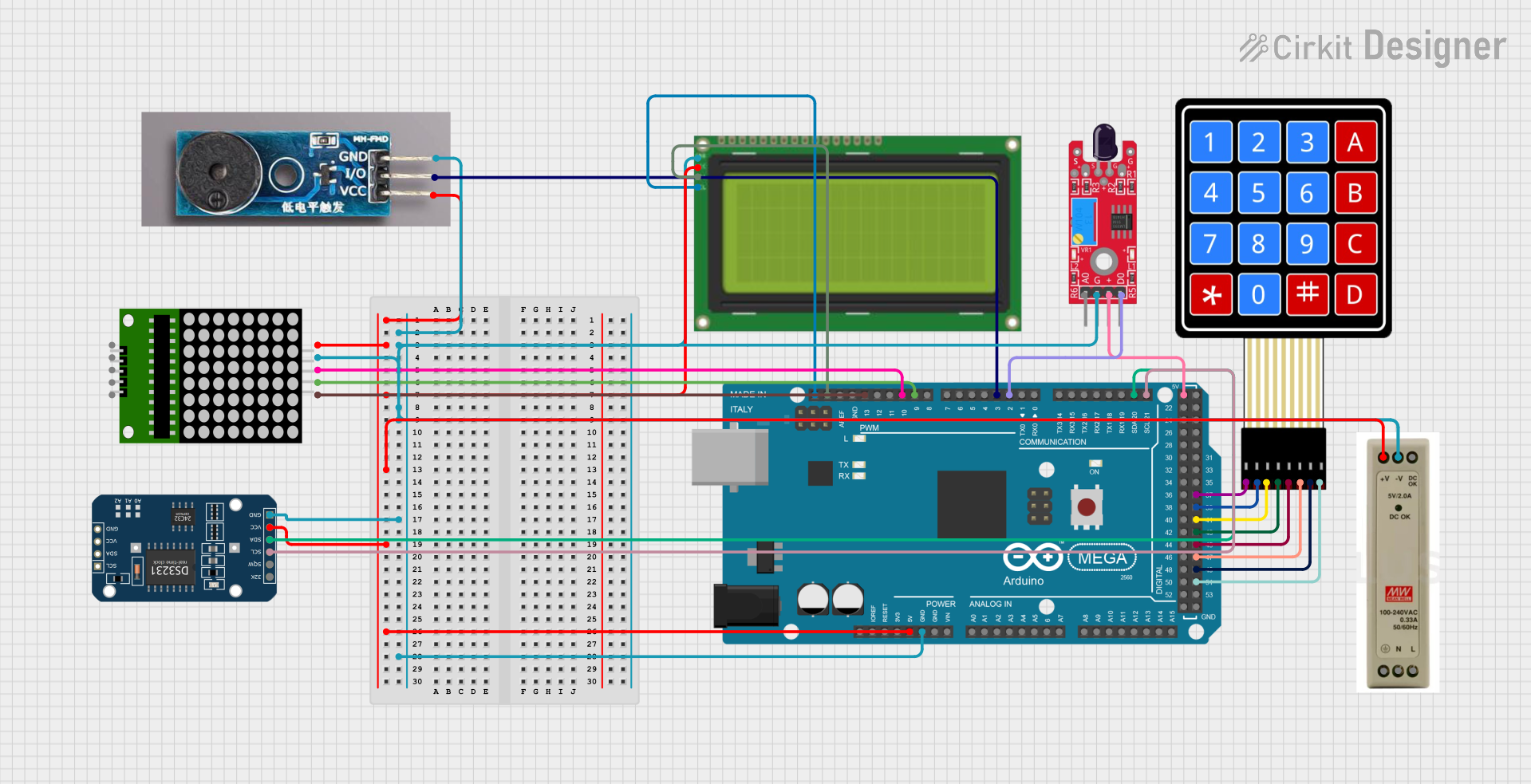
Arduino Mega 2560-Based Smart Home Control System with LCD Display and Flame Sensor
Image of Copy of schoolproject (1): A project utilizing MAX4409 in a practical application
This circuit is a multi-functional embedded system featuring an Arduino Mega 2560 microcontroller that interfaces with a 4x4 membrane keypad, a 20x4 I2C LCD, an 8x8 LED matrix, a DS3231 RTC module, a passive buzzer, and a KY-026 flame sensor. The system is powered by a 5V PSU and is designed to provide real-time clock functionality, user input via the keypad, visual output on the LCD and LED matrix, and flame detection with an audible alert.
Cirkit Designer LogoOpen Project in Cirkit Designer
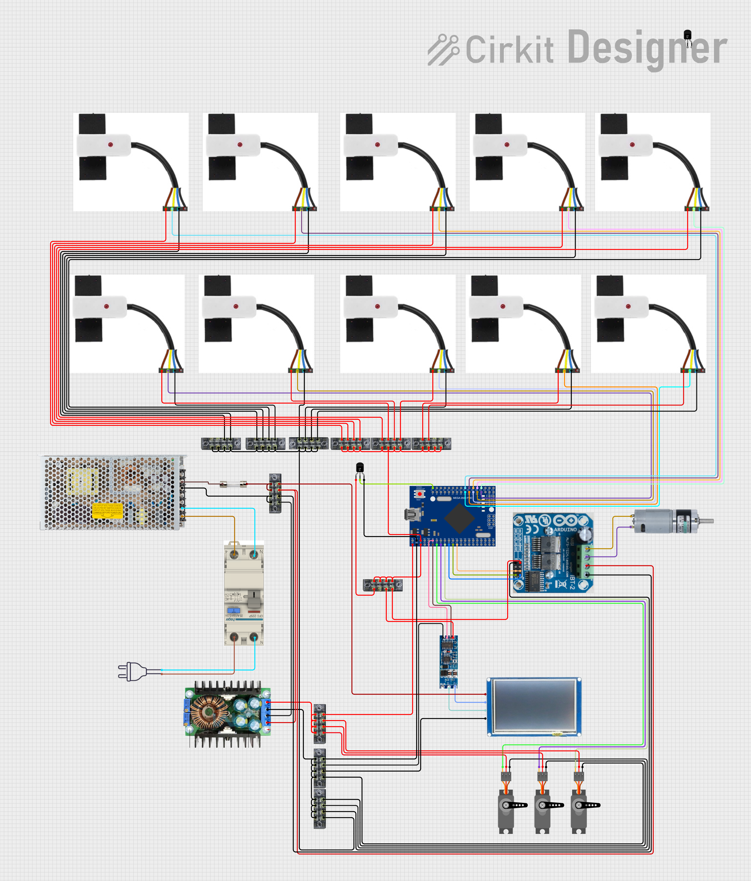
Mega2560-Controlled Automation System with Non-Contact Liquid Level Sensing and Motor Control
Image of Project_AutomaticBartender: A project utilizing MAX4409 in a practical application
This circuit appears to be a complex control system centered around an Arduino Mega2560 R3 Pro microcontroller, which interfaces with multiple sensors (XKC-Y26-V non-contact liquid level sensors and an LM35 temperature sensor), servo motors, a touch display, and an IBT-2 H-Bridge motor driver for controlling a planetary gearbox motor. The system also includes a UART TTL to RS485 converter for communication, likely with the touch display, and a power management subsystem with a switching power supply, fuses, and circuit breakers for safety and voltage regulation (XL4016). The absence of embedded code suggests that the functionality of the microcontroller is not defined within the provided data.
Cirkit Designer LogoOpen Project in Cirkit Designer
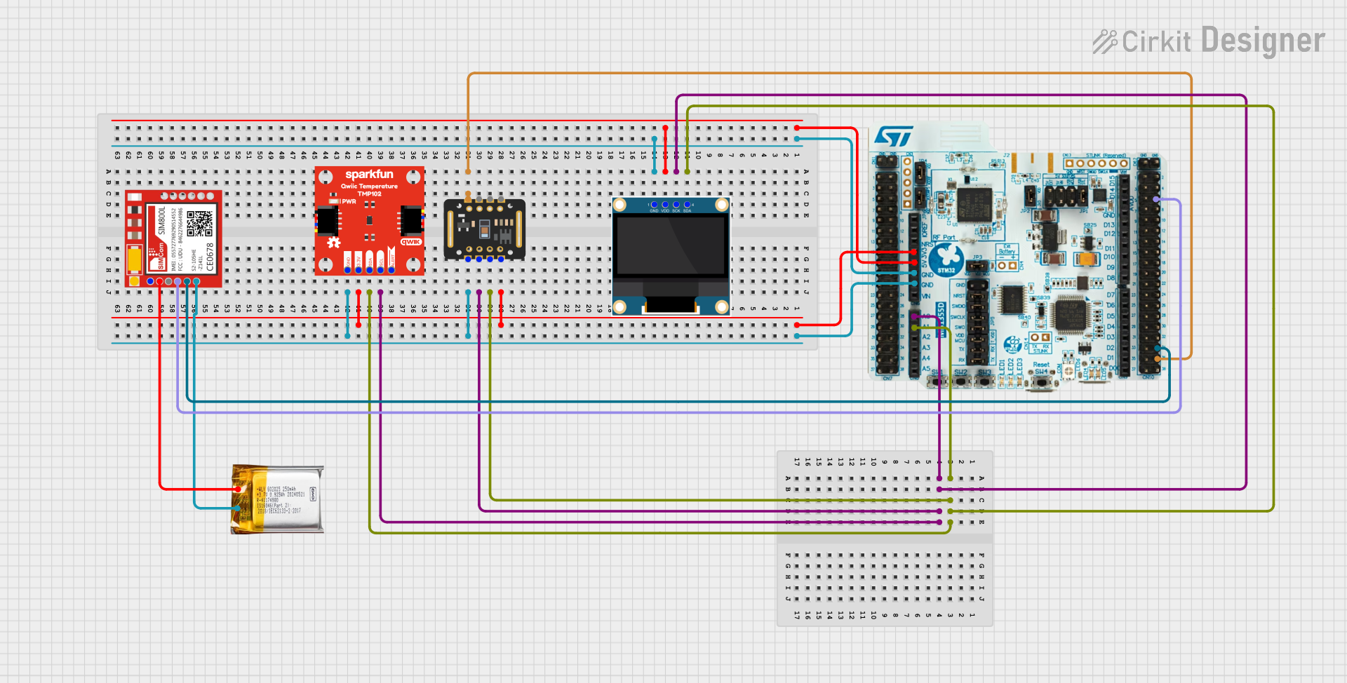
Battery-Powered Health Monitoring System with Nucleo WB55RG and OLED Display
Image of Pulsefex: A project utilizing MAX4409 in a practical application
This circuit is a multi-sensor data acquisition system that uses a Nucleo WB55RG microcontroller to interface with a digital temperature sensor (TMP102), a pulse oximeter and heart-rate sensor (MAX30102), and a 0.96" OLED display via I2C. Additionally, it includes a Sim800l module for GSM communication, powered by a 3.7V LiPo battery.
Cirkit Designer LogoOpen Project in Cirkit Designer

Explore Projects Built with MAX4409

Use Cirkit Designer to design, explore, and prototype these projects online. Some projects support real-time simulation. Click "Open Project" to start designing instantly!
Image of LRCM PHASE 2 BASIC: A project utilizing MAX4409 in a practical application
Cellular-Enabled IoT Device with Real-Time Clock and Power Management
This circuit features a LilyGo-SIM7000G module for cellular communication and GPS functionality, interfaced with an RTC DS3231 for real-time clock capabilities. It includes voltage sensing through two voltage sensor modules, and uses an 8-channel opto-coupler for isolating different parts of the circuit. Power management is handled by a buck converter connected to a DC power source and batteries, with a fuse for protection and a rocker switch for on/off control. Additionally, there's an LED for indication purposes.
Cirkit Designer LogoOpen Project in Cirkit Designer
Image of Copy of schoolproject (1): A project utilizing MAX4409 in a practical application
Arduino Mega 2560-Based Smart Home Control System with LCD Display and Flame Sensor
This circuit is a multi-functional embedded system featuring an Arduino Mega 2560 microcontroller that interfaces with a 4x4 membrane keypad, a 20x4 I2C LCD, an 8x8 LED matrix, a DS3231 RTC module, a passive buzzer, and a KY-026 flame sensor. The system is powered by a 5V PSU and is designed to provide real-time clock functionality, user input via the keypad, visual output on the LCD and LED matrix, and flame detection with an audible alert.
Cirkit Designer LogoOpen Project in Cirkit Designer
Image of Project_AutomaticBartender: A project utilizing MAX4409 in a practical application
Mega2560-Controlled Automation System with Non-Contact Liquid Level Sensing and Motor Control
This circuit appears to be a complex control system centered around an Arduino Mega2560 R3 Pro microcontroller, which interfaces with multiple sensors (XKC-Y26-V non-contact liquid level sensors and an LM35 temperature sensor), servo motors, a touch display, and an IBT-2 H-Bridge motor driver for controlling a planetary gearbox motor. The system also includes a UART TTL to RS485 converter for communication, likely with the touch display, and a power management subsystem with a switching power supply, fuses, and circuit breakers for safety and voltage regulation (XL4016). The absence of embedded code suggests that the functionality of the microcontroller is not defined within the provided data.
Cirkit Designer LogoOpen Project in Cirkit Designer
Image of Pulsefex: A project utilizing MAX4409 in a practical application
Battery-Powered Health Monitoring System with Nucleo WB55RG and OLED Display
This circuit is a multi-sensor data acquisition system that uses a Nucleo WB55RG microcontroller to interface with a digital temperature sensor (TMP102), a pulse oximeter and heart-rate sensor (MAX30102), and a 0.96" OLED display via I2C. Additionally, it includes a Sim800l module for GSM communication, powered by a 3.7V LiPo battery.
Cirkit Designer LogoOpen Project in Cirkit Designer

Common Applications and Use Cases

  • Portable devices (e.g., smartphones, tablets)
  • Display backlighting control
  • Automatic brightness adjustment
  • Industrial lighting systems
  • Consumer electronics

Technical Specifications

Key Technical Details

Parameter Value
Supply Voltage (Vcc) 1.7V to 3.6V
Operating Current 0.65µA (typical)
Lux Range 0.045 lux to 188,000 lux
I2C Address 0x4A (7-bit)
Output Type I2C Digital Output
Operating Temperature -40°C to +85°C

Pin Configuration and Descriptions

Pin Number Pin Name Description
1 VCC Power Supply (1.7V to 3.6V)
2 GND Ground
3 SCL I2C Clock Line
4 SDA I2C Data Line
5 INT Interrupt Output (optional, not always used)

Usage Instructions

How to Use the MAX4409 in a Circuit

  1. Power Supply: Connect the VCC pin to a power supply within the range of 1.7V to 3.6V. Connect the GND pin to the ground of the circuit.
  2. I2C Communication: Connect the SCL (clock) and SDA (data) lines to the corresponding I2C pins on your microcontroller. Pull-up resistors (typically 4.7kΩ) are recommended on both the SCL and SDA lines.
  3. Interrupt (Optional): If you wish to use the interrupt feature, connect the INT pin to a digital input on your microcontroller.

Important Considerations and Best Practices

  • Power Consumption: The MAX4409 is designed for low power consumption, making it ideal for battery-operated devices. Ensure that your power supply is stable and within the specified range.
  • I2C Address: The default I2C address for the MAX4409 is 0x4A. Ensure that this address does not conflict with other devices on the same I2C bus.
  • Ambient Light Conditions: Place the sensor in a location where it can accurately measure ambient light without obstructions.

Example Code for Arduino UNO

#include <Wire.h>

#define MAX4409_ADDRESS 0x4A // I2C address of MAX4409

void setup() {
  Wire.begin(); // Initialize I2C communication
  Serial.begin(9600); // Initialize serial communication
}

void loop() {
  uint16_t lux = readLightLevel();
  Serial.print("Ambient Light Level: ");
  Serial.print(lux);
  Serial.println(" lux");
  delay(1000); // Wait for 1 second before next reading
}

uint16_t readLightLevel() {
  Wire.beginTransmission(MAX4409_ADDRESS);
  Wire.write(0x03); // Command to read light level
  Wire.endTransmission();
  Wire.requestFrom(MAX4409_ADDRESS, 2); // Request 2 bytes from sensor

  if (Wire.available() == 2) {
    uint8_t msb = Wire.read(); // Read most significant byte
    uint8_t lsb = Wire.read(); // Read least significant byte
    uint16_t lux = (msb << 8) | lsb; // Combine bytes to form lux value
    return lux;
  } else {
    return 0; // Return 0 if no data is available
  }
}

Troubleshooting and FAQs

Common Issues and Solutions

  1. No Data from Sensor:

    • Check Connections: Ensure that all connections are secure and correct.
    • I2C Address Conflict: Verify that no other devices on the I2C bus share the same address (0x4A).
  2. Incorrect Light Readings:

    • Sensor Placement: Ensure the sensor is not obstructed and is placed in an appropriate location to measure ambient light.
    • Power Supply: Verify that the power supply voltage is within the specified range (1.7V to 3.6V).
  3. I2C Communication Issues:

    • Pull-up Resistors: Ensure that pull-up resistors are used on the SCL and SDA lines.
    • I2C Speed: Check that the I2C bus speed is compatible with the MAX4409.

FAQs

Q: Can the MAX4409 be used in outdoor applications? A: Yes, the MAX4409 can be used in outdoor applications, but it should be protected from direct exposure to harsh environmental conditions.

Q: What is the maximum distance for I2C communication with the MAX4409? A: The maximum distance for I2C communication depends on the bus speed and the quality of the wiring. Generally, it is recommended to keep the distance short (less than 1 meter) to ensure reliable communication.

Q: How can I reduce power consumption further? A: To reduce power consumption, ensure that the sensor is in a low-power state when not actively measuring light. This can be managed through the microcontroller's power management features.


This documentation provides a comprehensive guide to using the MAX4409 ambient light sensor. Whether you are a beginner or an experienced user, following these instructions and best practices will help you integrate the sensor effectively into your projects.