How to Use Coin Hopper: Examples, Pinouts, and Specs
Introduction
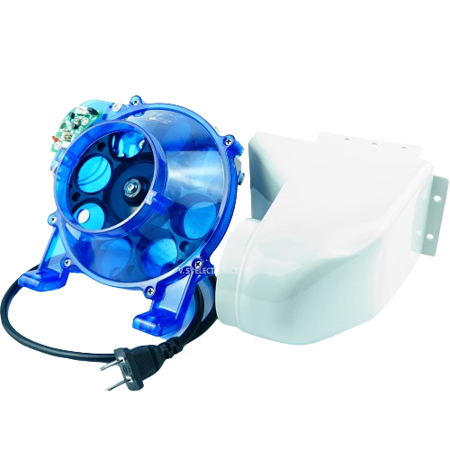
A coin hopper is an essential component in various coin-operated systems such as vending machines, arcade gaming machines, and slot machines. It serves as a storage and dispensing mechanism for coins, ensuring that the correct amount of change or payout is given to the user. The hopper will collect coins, sort them if necessary, and dispense them on command, typically through an electronic signal.
Explore Projects Built with Coin Hopper
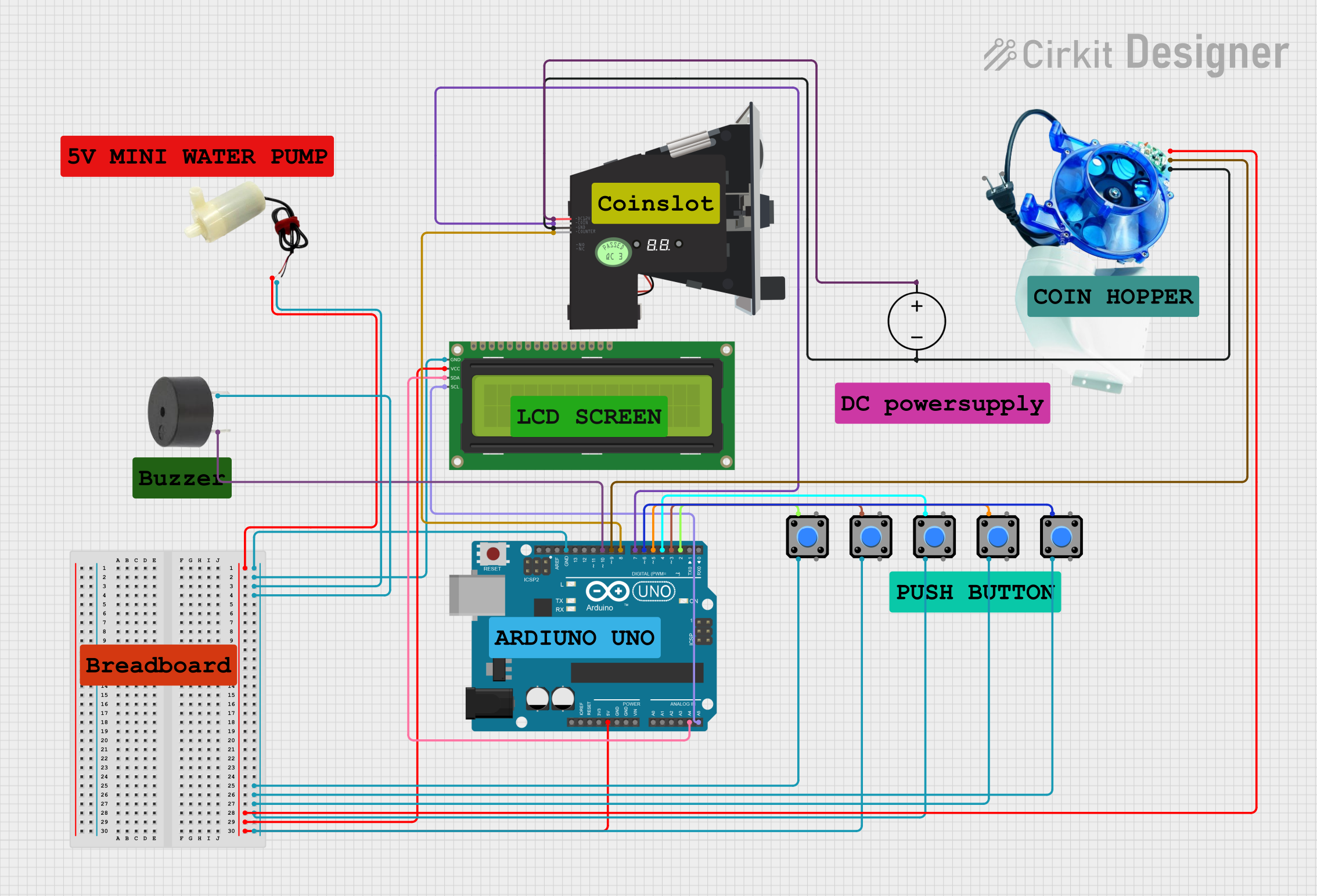

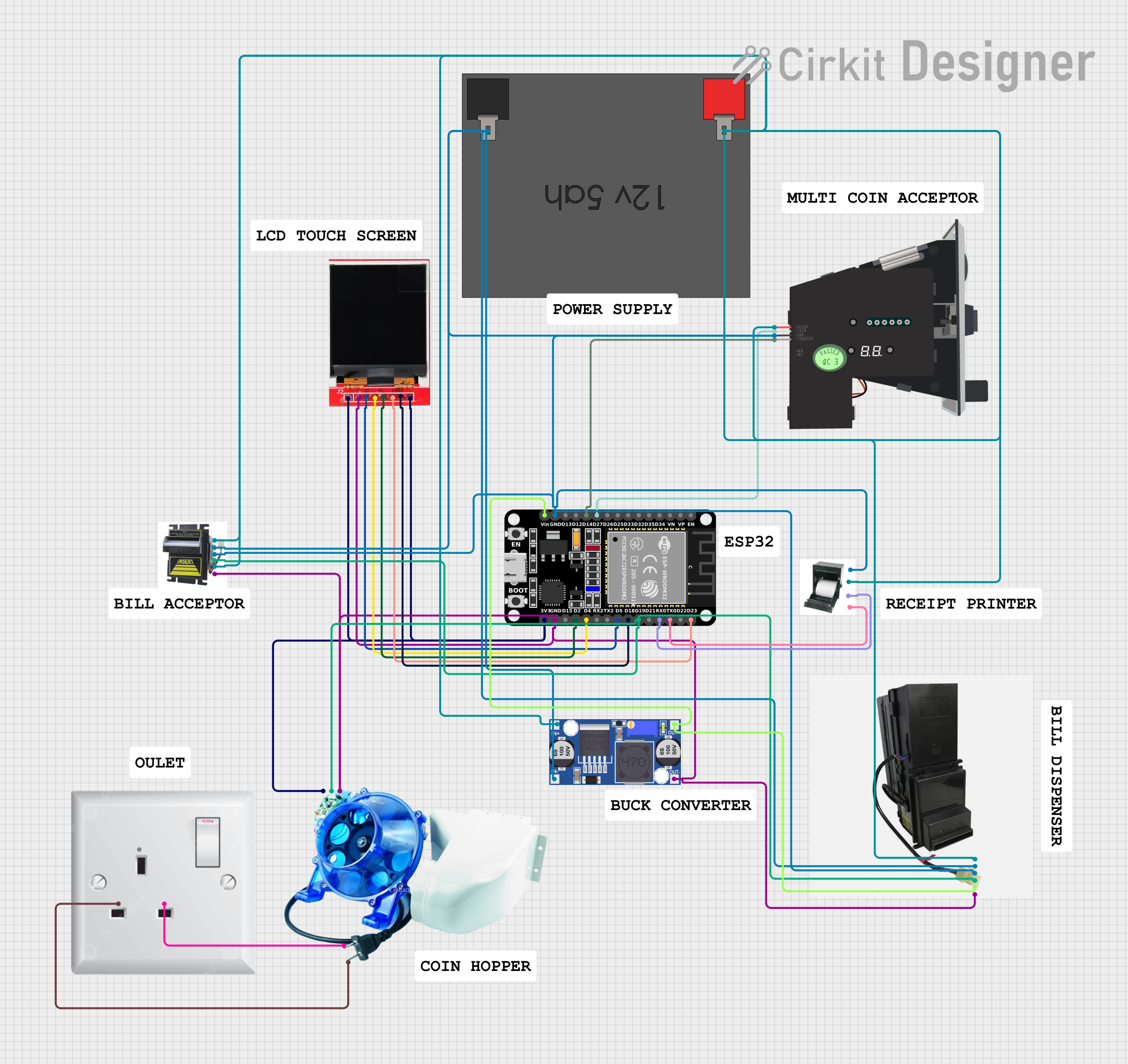
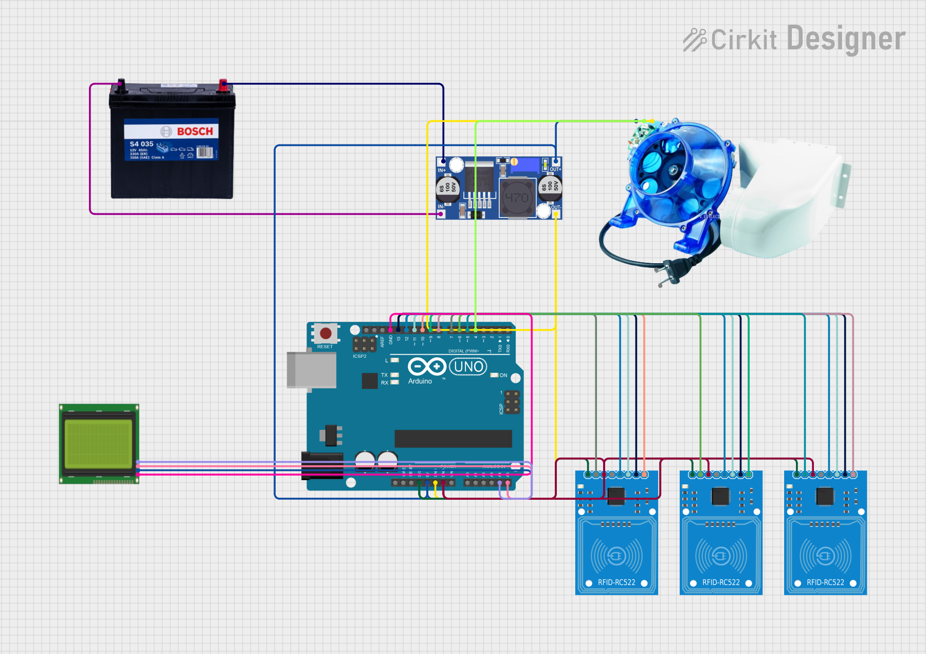
Explore Projects Built with Coin Hopper
Common Applications and Use Cases
- Vending machines for dispensing change
- Arcade machines for token payouts
- Slot machines for cash payouts
- Coin counting and sorting machines
- Automated teller machines (ATMs) for dispensing coins
Technical Specifications
Key Technical Details
- Voltage: Typically 12V or 24V DC
- Current: Varies depending on the model and coin load
- Dispensing Speed: Number of coins per second/minute
- Coin Capacity: Maximum number of coins the hopper can hold
- Coin Size Range: Diameter and thickness range of coins that can be used
- Interface: Usually a multi-pin connector for control signals
Pin Configuration and Descriptions
| Pin Number | Description | Notes |
|---|---|---|
| 1 | Ground | Connect to system ground |
| 2 | Power Supply (+12V or +24V) | Check hopper specifications |
| 3 | Coin Dispense Signal | Active high/low based on design |
| 4 | Coin Count Output | Pulse output for each coin |
| 5 | Error Signal Output | Indicates operational errors |
| 6 | Enable/Disable Hopper | Control signal to activate hopper |
Usage Instructions
How to Use the Coin Hopper in a Circuit
Power Connections: Connect the power supply pin to a suitable DC voltage source as per the hopper's specifications, and connect the ground pin to the system ground.
Control Signal: The coin dispense signal is used to trigger the dispensing mechanism. This can be connected to a microcontroller or other control systems.
Coin Counting: The coin count output sends a pulse for each coin dispensed, which can be used for auditing and ensuring the correct payout.
Error Handling: Monitor the error signal output to detect and respond to any operational issues.
Important Considerations and Best Practices
- Ensure that the power supply matches the voltage and current requirements of the coin hopper.
- Regularly clean and maintain the hopper to prevent jamming and ensure accurate coin dispensing.
- Test the hopper with the specific coins it will be dispensing to ensure compatibility.
- Use debounce circuits or software techniques to accurately count coins from the pulse output.
Troubleshooting and FAQs
Common Issues
- Coin Jamming: Coins may get stuck in the hopper. Regular maintenance and cleaning can prevent this.
- Inaccurate Coin Count: Ensure that the coin count sensor is clean and functioning correctly.
- No Power: Verify that the power supply is connected and delivering the correct voltage.
Solutions and Tips for Troubleshooting
- Jamming: Turn off the machine, remove the hopper, and clear any obstructions.
- Inaccurate Count: Check for debris on the sensor and recalibrate if necessary.
- Power Issues: Check all connections and the power source for proper voltage and current.
FAQs
Q: Can the coin hopper work with different coin denominations? A: Yes, but it must be calibrated and sometimes physically adjusted for the specific coin size range.
Q: How do I know if the coin hopper is dispensing the correct amount? A: Use the coin count output to verify the number of coins dispensed during each operation.
Q: What should I do if the coin hopper is not responding to the control signal? A: Check the connections and ensure that the enable/disable signal is set correctly. Also, verify that the control signal is within the specified voltage range.
Example Code for Arduino UNO
// Define pin connections
const int coinDispensePin = 3; // Coin Dispense Signal connected to digital pin 3
const int coinCountPin = 2;    // Coin Count Output connected to digital pin 2

// Variables
volatile int coinCount = 0;

// Interrupt service routine for coin counting
void countCoin() {
  coinCount++;
}

void setup() {
  pinMode(coinDispensePin, OUTPUT);
  pinMode(coinCountPin, INPUT_PULLUP);
  attachInterrupt(digitalPinToInterrupt(coinCountPin), countCoin, RISING);
}

void loop() {
  // Dispense coins (example: dispense 5 coins)
  for (int i = 0; i < 5; i++) {
    digitalWrite(coinDispensePin, HIGH); // Activate coin dispense
    delay(100);                          // Wait for the coin to dispense
    digitalWrite(coinDispensePin, LOW);  // Deactivate coin dispense
    delay(1000);                         // Wait between coin dispenses
  }

  // Check coin count
  if (coinCount >= 5) {
    // Expected number of coins have been dispensed
    // Reset coin count and perform other tasks
    coinCount = 0;
  }

  // Add additional logic as needed
}
Note: The above code is a simple example to demonstrate how to control a coin hopper and count coins using an Arduino UNO. The actual implementation may vary based on the specific hopper model and application requirements. Always refer to the hopper's datasheet for precise control signal specifications.